
Gas Furnace Installation Instructions
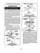
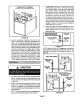
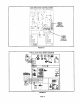

On roof terminations, the intake piping should termi-
nate straight down using two 90° elbows. See figure 8.
NOTE - If winter design temperature is below 32°F (O°C),
exhaust piping must be insulated with 1/2 inch (13 mm)
Armaflex or equivalent when run through unheated
space. Do not leave any surface area of exhaust pipe
open to outside air," exterior exhaust pipe must be insu-
lated with 1/2 inch (13 ram) Armaflex or equivalent. In ex-
treme cold climate areas, 3/4 inch (19 mm) Armaflex or
equivalent is recommended. Insulation on outside runs of
exhaust pipe must be painted or wrapped to protect in-
sulation from deterioration.
NOTE - During extremely cold temperatures, below
approximately 20°F (6.67°C), units with long runs of vent
pipe through unconditioned space, even when insulated,
may form ice in the exhaust termination that prevents the
unit from operating properly. Longer run times of at least 5
minutes will alleviate most icing problems. Also, a heating
cable may be installed on exhaust piping and termination
to prevent freeze-ups. Heating cable installation kit is
available from Lennox. See Condensate Piping section
for part numbers.
NOTE - Care must be taken to avoid recirculation of ex-
haust back into intake pipe.
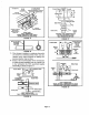
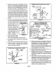
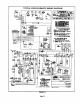
6 - On field-supplied terminations for side wall exits, ex-
haust piping should extend a maximum of 12 inches
(305 mm) beyond the outside wall. Intake piping
should be as short as possible. See figure 10.
IMAX.
Inches (ram) 3 x 2 (70 x 51) OR
2 x %1/2 (51 x 38)
PVC REDUCER
1/2 (13) FOAM
INSULATION IN
UNCONDrrlONED
12 (305) ABOVE SPACE
AVERAGE SNOW
ACCUMULATION
3 (76) OR UNCONDmONED
2 (5t) PVC ATTIC SPACE
PROVIDE SUPPORT
FOR INTAKE AND
F.XHAUST LINES
ROOFTERMINATIONKIT
(15F'75)LB-49107CCfor 2 (5t) Venting
(44341)LB-65678Afor 3 (76)Venting
FIGURE 8
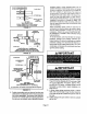
EXHAUST
12 (305) ABOVE
AVERAGE SNOW
ACCUMULATION
INTAKE
TERMINATION
Inches (mm)
EXHAUST INTAKE
CONCENTRIC ROOFTOP TERMINATION
(60G77) LB-49107CE for G32-75 Units Only
(33K97) LB-87942 for G32-100 & -125 Units Only
FIGURE 9
1/2 (13) ARMAFLEX
INSULATION IN
UNCONDITIONED SPACE
1/2 (13) ARMAFLEX t'
INSULATION
OUTSIDE j
WALL
12 (305) MIN.
2 X 1-1/2
(51 X 38)
PV REDUCER
_ _ 'VC
I 6 (I 52)
MAXIMUM
_ 2 (_ I PVC
PLING
Inches (ram)
7-
8-
TOPVIEW
WALLRINGKIT
(15J74) LB-49107CBfor2 (50,8 ! Venting
FIGURE 10
On field-supplied terminations, a minimum separa-
tion distance between the end of the exhaust pipe
and the end of the intake pipe is 8 inches (203 mm).
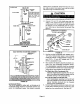
If intake and exhaust piping must be run up a side
wall to position above snow accumulation or other
obstructions, the piping must be supported every 3
feet (.91 m) as shown in figure 15. Refer to figures 13
and 14 for proper piping method. W'FKwall termina-
tion kit must be extended for use in this application,
See figure 18 or use kit WTKX shown in figure 19.
When exhaust and intake piping must be run up an
outside wall, the exhaust piping is reduced to 1-1/2
inches (38 mm) after the final elbow. The intake pip-
ing may be equipped with a 90°elbow turndown. Us-
ing 90° turndown will add 5 feet (1.5 m) to the equiva-
lent length of the pipe.
Page 11