
Gas Furnace Installation Instructions


Model No.
G32-75 natura_
G32-100 natural
G32-125 natural
G32-75 L.P
G32-100 L,P.
G32-125 L,P.
0 to 4500 ft. (0 to 1372 m)
above sea level
3.8
3.5 (0.87)
7.5
7.5 (1.90)
7.5 11.90)
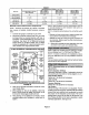
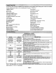
TABLE 6
Manifold Pressure (outlet) in.w.g (kPa)
4501 to 5500 ft.
(1373 to 1676 m)
above sea level
3,5
34(0.85)
7.5
7.3 (1.81)
7.3 (1.81 }
5501 to 6500 ft.
(1677 to 1981 m)
above sea level
35
3.3 (0.82)
7.5
7.1 (1.80)
7.1 (1.8o)
6501 to 7500ft,
(1982to2286 m)
above sea level
3.5
3.2 (0.80)
7.5
7.0 (1.74)
7.0 (1.74)
Manifold Pressure Measurement & Adjustment
NOTE - Pressure test adaptor kit (10L34) is available
from Lennox to facilitate manifold pressure measure-
ment.
1 - Connect test gauge to outlet tap on gas valve.
2 - Disconnect pressure sensing hose from gas valve
and plug hose by covering opening with tape or
equivalent. Leave barbed fitting on valve open to at-
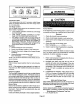
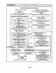
mosphere. See figure 35 for differential pressure
switch circuitry on 75 kBtuh models. Only 75 kBtuh
models are equipped with a secondpressure switch.
Other models have single pressure switch.
75 kBtuhDIFFERENTIALPRESSURESWITCHCIRCUITRY
BURNER
BOX
LOW HEAT
DIFFERENTIAL
PRESSURE BARS
SWITCH
TEE
HIGH HEAT
DIFFERENTIAL
PRESSURE
SWITCH
COMBUSllON
AIR PRESSURE
SENSING HOSE
SOX
SENSING
HOSE
GAS
VALVE
SENSING
HOSE
GAS
VALVE
COMBUSTION
AIR INOUCER PRESSURE
HONEYWELL PPS SWITCH
PRESSURE SENSING
SWITCH HOSE
SHOWN
LEFT SIO_ OF PRESSURE SWITCH = MORE NEGATIVE
RIGH'r SIDE OF PRESSURE SWITCH = LESS NEGATIVE (Closer to Zero)
FIGURE 35
3 - Start uniton high heat and allow 5 minutes for unitto
reach steady state.
4- While waiting for the unit to stabilize, notice the
flame. Flame should be stable and should not lift
from burner. Natural gas shouldbum blue.
5 - After allowing unit to stabilize for 5 minutes, record
manifold pressure and compare to value given in
table 6.
NOTE - Shut unit off and remove manometer as soon as
an accurate reading has been obtained. Takecare to re-
place pressure tap plug.
NOTE - During this test procedure, the unit will be overt/r-
ing:
• Operate unit only long enough to obtain accurate read-
ing to prevent overheating heat exchanger.
• Attempts to clock gas valve during this procedure will
be inaccurate. Measure gas flow rate only during nor-
mal unit operation.
6 - When test is complete remove obstruction from hose
and return hose to gas valve barbed fitting.
Refer to table 6 for manifold pressuresettings for installa-
tions at altitudes from 0 to 7500 feet (0 to 2286 m).
NOTE - In Canada, certification for installations at eleva-
tions over 4500 feet (1372 m) is thejurisdiction of local au-
thorities.
The two pressure switches (high and low heat) are factory
set and are not to be adjusted.
NOTE - Disconnect power to unit before making any
adjustments.
Heat Anticipation Settings
Thermostat anticipatorsetting (if adjustable) should be
set accordingto amps listed on widngdiagram on unit.
Flame Rollout Switch
Factory set: No adjustment necessary.
Limit Control
Factory set: No adjustmentnecessary.
Pressure Switches
Factory set: No adjustmentis necessary.
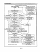
Fan Control
The fan-on delayof 45 secondsis notadjustable.The fan-
off delay (time that the blower operates after the heating
demand has been satisfied) can be adjustedby moving
the jumper on the integrated control board. The unit is
shipped witha factory fan-off delay of 180 seconds.The
fan-off delay will affectcomfort and is adjustableto satisfy
individual applications. See figure 36.
Page 23