INSTALLATION INSTRUCTIONS E 2009 Lennox Industries Inc. Dallas, Texas, USA G61MP SERIES UNITS GAS UNITS 506406−01 08/2009 Supersedes 505,124M Litho U.S.A. Table of Contents Unit Dimensions . . . . . . . . . . . . . . . . . . . . . . . . . . . . . . . G61MP Parts Identification . . . . . . . . . . . . . . . . . . . . . . Shipping and Packing List . . . . . . . . . . . . . . . . . . . . . . Safety Information . . . . . . . . . . . . . . . . . . . . . . . . . . . . . Use of Furnace as Construction Heater .
G61MP Unit Dimensions − inches (mm) *NOTE − 60C and 60D size units installed in upflow applications that require air volumes over 1800 cfm (850 L/s) must have one of the following: 1. Single side return air with transition, to accommodate 20 x 25 x 1 in. (508 x 635 x 25 mm) air filter. Required to maintain proper air velocity. 2. Single side return air with optional RAB Return Air Base 3. Bottom return air. 4. Return air from both sides. 5. Bottom and one side return air.
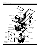
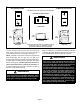
G61MP Parts Arrangement G61MP PARTS IDENTIFICATION TOP CAP DuralokPlusTM HEAT EXCHANGER ASSEMBLY CABINET BURNER BOX ASSEMBLY GAS VALVE AND MANIFOLD FLUE COLLAR COMBUSTION AIR PRESSURE PROVE SWITCHES* WARM HEADER (COLLECTOR) BOX COMBUSTION AIR INDUCER CONDENSER COIL BURNER ACCESS PANEL PRIMARY LIMIT COLD HEADER (COLLECTOR) BOX BLOWER ACCESS DOOR *G61MP−090 shown. G61MP−045 and −070 are equipped with two switches.
G61MP Gas Furnace The G61MP category IV gas furnace is shipped ready for installation in the upflow, downflow, horizontal left air discharge or horizontal right air discharge position. The furnace is shipped with the bottom panel in place. The bottom panel must be removed if the unit is to be installed in upflow applications with bottom return air. The bottom panel must also be removed and discarded in all downflow or horizontal applications.
In Canada, installation must conform with current National Standard of Canada CSA-B149 Natural Gas and Propane Installation Codes, local plumbing or waste water codes and other applicable local codes. In order to ensure proper unit operation in non−direct vent applications, combustion and ventilation air supply must be provided according to the current National Fuel Gas Code or CSA-B149 standard.
D D D One hundred percent (100%) outdoor air must be provided for combustion air requirements during construction. Temporary ducting may supply outdoor air to the furnace. Do not connect duct directly to the furnace. Size the temporary duct following these instructions in section for Combustion, Dilution and Ventilation Air in a confined space with air from outside.
Z223.1/NFPA 54). This reprinted material is not the complete and official position of the ANSI on the referenced subject, which is represented only by the standard in its entirety. In Canada, refer to the standard CSA B149 installation codes. CAUTION Do not install the furnace in a corrosive or contaminated atmosphere. Meet all combustion and ventilation air requirements, as well as all local codes. All gas-fired appliances require air for the combustion process.
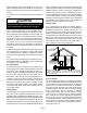
EQUIPMENT IN CONFINED SPACE − ALL AIR FROM OUTSIDE (Inlet Air from Crawl Space and Outlet Air to Ventilated Attic) VENTILATION LOUVERS (Each end of attic) ROOF TERMINATED EXHAUST PIPE OUTLET AIR SIDE WALL TERMINATED EXHAUST PIPE (ALTERNATE LOCATION) G61MP INLET AIR VENTILATION LOUVERS (For unheated crawl space) NOTE−The inlet and outlet air openings shall each have a free area of at least one square inch per 4,000 Btu (645mm2 per 1.
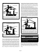
SETTING EQUIPMENT UPFLOW APPLICATION DOWNFLOW APPLICATION UNIT MUST BE LEVEL SIDE−TO−SIDE IN ALL APPLICATIONS. AIR FLOW HORIZONTAL APPLICATION AIR FLOW AIR FLOW FRONT VIEW FRONT VIEW FRONT VIEW AIR FLOW UNIT FRONT UNIT FRONT UNIT FRONT 1/2" max. AIR FLOW END VIEW 1/2" max. SIDE VIEW 1/2" max. UNIT SHOULD BE LEVEL FROM LEFT TO RIGHT BUT MAY BE TILTED SLIGHTLY (MAX. 1/2") FROM BACK TO FRONT TO AID IN THE DRAINING OF THE HEAT EXCHANGER.
Upflow Applications Return Air −− Upflow Units The G61MP gas furnace can be installed as shipped in the upflow position. Refer to figure 8 for clearances. Return air can be brought in through the bottom or either side of the furnace installed in an upflow application. If the furnace is installed on a platform with bottom return, make an airtight seal between the bottom of the furnace and the platform to ensure that the furnace operates properly and safely.
Optional Return Air Base (Upflow Applications Only −− For use with B, C and D cabinets only) 14 (356) AIR FLOW FURNACE FRONT 23 (584) Overall (Maximum) 1 OPTIONAL RAB RETURN AIR BASE 1 Minimum 11 (279) Maximum Unit side return air 14 (356) Opening 2 5−5/8 (143) 7−1/4 (184) 17−1/2 (446) RAB−B (98M60) 21 (533) RAB−C (98M58) 24−1/2 (622) RAB−D (98M59) 1 4 (102) 1 22−7−16 (570) Overall (Maximum) SIDE RETURN AIR OPENINGS (Either Side) 3/4 (19) 23 (584) 7/8 (22) FRONT VIEW 27−5/8 (702) SIDE VIE
Setting an Upflow Unit When the side return air inlets are used in an upflow application, it may be necessary to install leveling bolts on the bottom of the furnace. Use field−supplied corrosion−resistant 5/16 inch machine bolts (4) and nuts (8). See figure 12. Refer to figure 13 for clearances in downflow applications. Downflow Application Installation Clearances Top NOTE − The maximum length of the bolt is 1−1/2 inches.
Installation on Combustible Flooring (Using an Additive Base) 1 − When unit is installed on a combustible floor, an additive base must be installed between the furnace and the floor. The base must be ordered separately. See table 2 for opening size to cut in floor. CAUTION The furnace and additive base shall not be installed directly on carpeting, tile, or other combustible material other than wood flooring. TABLE 2 ADDITIVE BASE FLOOR OPENING SIZE Cabinet Width Catalog Number B Cabinet (17.
Horizontal Applications The G61MP furnace can be installed in horizontal applications with either right− or left−hand air discharge. The G61MP may also be installed as a unit heater. Either suspend the furnace as shown in figure 18, or install the furnace on a field−fabricated raised platform. The unit must be supported at both ends and beneath the blower deck to prevent sagging. Refer to figure 17 for clearances in horizontal applications.
Lennox part number 56J18). Position the support frame on top of the blocks and install the unit on the frame. Leave 5−1/2 inches for service clearance for condensate trap. 3 − Route auxiliary drain line so that water draining from this outlet will be easily noticed by the homeowner. If necessary, run the condensate line into a condensate pump to meet drain line slope requirements. The pump must be rated for use with condensing furnaces.
Filters Pipe & Fittings Specifications This unit is not equipped with a filter or rack. A field−provided filter is required for the unit to operate properly. Table 3 lists recommended filter sizes. A filter must be in place whenever the unit is operating.
Use PVC primer and solvent cement or ABS solvent cement meeting ASTM specifications, refer to Table 4. As an alternate, use all purpose cement, to bond ABS, PVC, or CPVC pipe when using fittings and pipe made of the same materials. Use transition solvent cement when bonding ABS to either PVC or CPVC. Low temperature solvent cement is recommended. Metal or plastic strapping may be used for vent pipe hangers.
Vent Piping Guidelines The G61MP can be installed as either a Non−Direct Vent or a Direct Vent gas central furnace. NOTE − In Non-Direct Vent installations, combustion air is taken from indoors and flue gases are discharged outdoors. In Direct Vent installations, combustion air is taken from outdoors and flue gases are discharged outdoors. Intake and exhaust pipe sizing in Direct Vent applications and exhaust pipe sizing in Non-Direct Vent applications −− Size pipe according to tables 6 and 7.
Use the following steps to correctly size vent pipe diameter. Refer to Vent Pipe Size Determination Worksheet on page 53. 1 − Determine the vent termination and its corresponding equivalent feet value according to table 5. 2 − Determine the number of 90° elbows required for both indoor and outdoor (e.g. snow riser) use. Calculate the corresponding equivalent feet of vent pipe. 3 − Determine the number of 45° elbows required for both indoor and outdoor use.
Joint Cementing Procedure All cementing of joints should be done according to the specifications outlined in ASTM D 2855. WARNING NOTE − Furnace flue collar and air inlet fitting are both made of ABS material. Use transition solvent cement when bonding ABS to either PVC or CPVC, refer to the procedure specified in ASTM D3138.. 6 − Promptly apply solvent cement to end of pipe and inside socket surface of fitting. Cement should be applied lightly but uniformly to inside of socket.
4 − Isolate piping at the point where it exits the outside wall or roof in order to prevent transmission of vibration to the structure. Venting Practices The thickness of construction through which vent pipes may be installed is 24" (610mm) maximum and 3" (76mm) minimum. If a G61MP furnace replaces a furnace which was commonly vented with another gas appliance, the size of the existing vent pipe for that gas appliance must be checked.
CAUTION TYPICAL EXHAUST PIPE CONNECTIONS HORIZONTAL DIRECT OR NON−DIRECT VENT APPLICATIONS (Horizontal Right−Hand Air Discharge Application Shown) * 2" maximum length for −110, −111 −135 only Do not discharge exhaust into an existing stack or stack that also serves another gas appliance. If vertical discharge through an existing unused stack is required, insert PVC pipe inside the stack until the end is even with the top or outlet end of the metal stack.
TYPICAL AIR INTAKE PIPE CONNECTIONS UPFLOW OR DOWNFLOW DIRECT VENT APPLICATIONS (Right−Hand Exit in Upflow Application Shown) 2−1/2", 3" OR 4 2 2 2 2 PLUG (Must be glued in place) 2−1/2", 3" OR 4 TRANSITION 2 −36B−045− −36B−070 −36B−071 −48C−090 −60C−090 −60C−091 TRANSITION *2" 2 −36B−045 −36B−070 −36B−071 −48C−090 −60C−090 −60C−091 −48C−110 −60C−110* −60C−111* −60D−135* −36B−045 −36B−070 −36B−071 −48C−090 −60C−090 −60C−091 −48C−110 −60C−110 −60C−111 *Limit pipe length to 4" in G61MP−
TYPICAL AIR INTAKE PIPE CONNECTIONS DOWNFLOW NON−DIRECT VENT APPLICATIONS (Right−Hand Exit in Downflow Applications Shown) 2" SWEEP ELL PLUG (Must be glued in place) INTAKE DEBRIS SCREEN (Provided) 6 in. Max. PLUG (Must be glued in place) 18 in. 2" SWEEP ELL INTAKE DEBRIS SCREEN (Provided) Downflow Evaporator Coil 2" Downflow Additive Flloor Base NOTE − Debris screen and sweep ell may be rotated, so that screen may be positioned to face forward, backward or to the side.
General Guidelines for Vent Terminations In Non-Direct Vent applications, combustion air is taken from indoors and the flue gases are discharged to the outdoors. The G61MP is then classified as a non-direct vent, Category IV gas furnace. In Direct Vent applications, combustion air is taken from outdoors and the flue gases are discharged to the outdoors. The G61MP is then classified as a direct vent, Category IV gas furnace.
VENT TERMINATION CLEARANCES FOR NON−DIRECT VENT INSTALLATIONS IN THE USA AND CANADA INSIDE CORNER DETAIL G H A D E B L Fixed Closed Operable F B B C Operable Fixed Closed I M B K J A B VENT TERMINAL A= Clearance above grade, veranda, porch, deck or balcony B= Clearance to window or door that may be opened C= Clearance to permanently closed window D= Vertical clearance to ventilated soffit located above the terminal within a horizontal distance of 2 feet (mm) from the center line of t
VENT TERMINATION CLEARANCES FOR DIRECT VENT INSTALLATIONS IN THE USA AND CANADA INSIDE CORNER DETAIL G H A D E B L Fixed Closed Operable F B B C I Fixed Closed Operable M B K J A B VENT TERMINAL A= Clearance above grade, veranda, porch, deck or balcony B= Clearance to window or door that may be opened C= Clearance to permanently closed window D= Vertical clearance to ventilated soffit located above the terminal within a horizontal distance of 2 feet (mm) from the center line of the
Details of Intake and Exhaust Piping Terminations for Direct Vent Installations NOTE − In Direct Vent installations, combustion air is taken from outdoors and flue gases are discharged to outdoors. Intake and exhaust pipes may be routed either horizontally through an outside wall or vertically through the roof. In attic or closet installations, vertical termination through the roof is preferred. Figures 31 through 39 show typical terminations.
EXHAUST TERMINATION EXHAUST VENT 12" (305) ABOVE AVERAGE SNOW ACCUMULATION Inches (mm) Front View INTAKE VENT INTAKE TERMINATION 1/2" (13) Foam Insulation in Unconditioned Space FIELD−PROVIDED REDUCER MAY BE REQUIRED TO ADAPT LARGER VENT PIPE SIZE TO TERMINATION EXHAUST FIELD− PROVIDED REDUCER MAY BE REQUIRED TO ADAPT LARGER VENT PIPE SIZE TO TERMINATION INTAKE DIRECT VENT CONCENTRIC ROOFTOP TERMINATION (71M80, 69M29 or 60L46) FIGURE 36 EXHAUST TERMINATION INTAKE EXHAUST VENT 12" (305) Min.
12" (305) MAX. for 2" (51) 20" (508) MAX. for 3" (76) (unless supported) Inches (mm) COVER EXHAUST VENT WITH 1/2" (13) FOAM INSULATION 12" (305) EXHAUST AIR 8" (203) Minimum INTAKE AIR INTAKE AIR Minimum 12" (305) above grade or average snow accumulation. Minimum 12" (305) above grade or average snow accumulation.
3 − If exhaust piping must be run up a side wall to position above snow accumulation or other obstructions, piping must be supported every 3 feet (.9m) as shown in figure 22. Refer to figure 42 for proper piping method. When exhaust piping must be run up an outside wall, any reduction in exhaust pipe size must be done after the final elbow. UNCONDITIONED SPACE OUTSIDE WALL Horizontal right and optional downflow SIZE TERMINATION PIPE PER TABLE 8.
NOTE − The condensate trap drain stubs (both sides) have an outer diameter which will accept a standard 3/4" PVC coupling. The inner diameter of each stub will accept standard 1/2" diameter PVC pipe. NOTE − Vinyl tubing may be used for condensate drain. Tubing must be 1−1/4" OD X 1" ID and should be attached to the drain stubs on the trap using a hose clamp. 4 − Glue the field−provided drain line to the tee. Route the drain line to an open drain.
Gas Piping IMPORTANT CAUTION If a flexible gas connector is required or allowed by the authority that has jurisdiction, black iron pipe shall be installed at the gas valve and extend outside the furnace cabinet. Compounds used on threaded joints of gas piping must be resistant to the actions of liquified petroleum gases. MANUAL MAIN SHUT−OFF VALVE WILL NOT HOLD NORMAL TEST PRESSURE WARNING ISOLATE GAS VALVE Do not exceed 600 in−lbs (50 ft−lbs) torque when attaching the gas piping to the gas valve.
Horizontal Applications Possible Gas Piping Configerations MANUAL MAIN SHUT−OFF VALVE Horizontal Application Left−Side Air Discharge MANUAL MAIN SHUT−OFF VALVE GROUND JOINT UNION GROUND JOINT UNION DRIP LEG DRIP LEG MANUAL MAIN SHUT−OFF VALVE (With 1/8 in. NPT Plugged Tap Shown) Horizontal Application Right−Side Air Discharge GROUND JOINT UNION DRIP LEG FIGURE 48 TABLE 9 GAS PIPE CAPACITY − FT3/HR (kL/HR) Length of Pipe−Feet(m) 50 60 70 (15.240) (18.288) (21.
The unit is equipped with a field make−up box. The make− up box may be moved to the right side of the furnace to facilitate installation. If the make−up box is moved to the right side, the excess wire must be pulled into the blower compartment. Secure the excess wire to the existing harness to protect it from damage. Electrical ELECTROSTATIC DISCHARGE (ESD) Precautions and Procedures CAUTION Electrostatic discharge can affect electronic components.
9 − One 24V H" terminal is provided on the furnace control board terminal block. Any humidifier rated up to 0.5 amp can be connected to this terminal with the ground leg of the circuit being connected to either ground or the C" terminal. See figure 52 for control board configuration. 10 −Install the room thermostat according to the instructions provided with the thermostat. See table 10 for field wiring connections in varying applications.
TABLE 10 Field Wiring Applications Thermostat 1 Heat / 1 Cool NOTE − Use DIP switch 2 to set second−stage heat ON delay. OFF10 minutes. ON−15 minutes. DIP Switch Settings and On−Board Links (Figure 52) W915 W951 (Y1 to Y2) DIP Switch 1 (O to R) Two−Stage Heat Pumps Cooling ON Intact Intact Wiring Connections S1 T’STAT CONTROL TERM. STRIP OUTDOOR UNIT EXISTING W915 JUMPER 1 Heat / 2 Cool NOTE − Use DIP switch 2 to set second−stage heat ON delay. OFF−10 minutes. ON−15 minutes.
TABLE 10 Field Wiring Applications (Continued) Thermostat DIP Switch Settings and On−Board Links (Figure 52) W915 W951 (Y1 to Y2) DIP Switch 1 (O to R) Two−Stage Heat Pumps Cooling Wiring Connections 2 Heat / 2 Cool OFF Cut Intact S1 T’STAT CONTROL TERM. STRIP OUTDOOR UNIT 2 Heat / 1 Cool OFF Intact Intact S1 T’STAT CONTROL TERM.
TWO−STAGE INTEGRATED CONTROL BOARD 1/4" QUICK CONNECT TERMINALS SENSE = 120 VAC OUTPUT TO FLAME SENSER NEUTRALS= 120 VAC NEUTRAL PARK = DEAD TERMINAL FOR UNUSED BLOWER LEAD HEAT LOW = 120 VAC OUTPUT TO CIRC BLWR −− LOW HT SPEED AND CONTINUOUS FAN HEAT HIGH/ COOL LOW = 120 VAC OUTPUT TO CIRC BLWR −− HIGH HEAT AND LOW COOL SPEED COOL HIGH = 120 VAC OUTPUT TO CIRC BLWR −− HIGH COOL SPEED DIAGNOSTIC LEDs THERMOSTAT CONNECTIONS (TB1) DIP SWITCHES ON−BOARD JUMPERS 1= ERROR CODE RECALL H= 24V HUMIDIFIER OUTPU
INTEGRATED CONTROL BOARD DIP SWITCH SETTINGS AND JUMPERS FIGURE 53 Page 40
TYPICAL G61MP WIRING DIAGRAM FIGURE 54 Page 41
TABLE 11 Heating Blower−Off Delay Switch Settings Integrated Control Board G61MP units are equipped with a two−stage integrated control. This control manages ignition timing and fan off delays based on selections made using the control DIP switches and jumpers. The control includes an internal watchguard feature which automatically resets the ignition control when it has been locked out.
4 − This furnace is equipped with an ignition device which automatically lights the burners. Do not try to light the burners by hand. 5 − Remove the upper access panel. 6 − White Rodgers 36E Gas Valve − Move gas valve switch to OFF. See figure 55 for the White Rodgers 36E valve. Honeywell VR8205 Gas Valve − Move switch on gas valve clockwise to OFF. Do not force. See figure 56. 7 − Wait five minutes to clear out any gas.
12− If the appliance will not operate, follow the instructions Turning Off Gas to Unit" and call your service technician or gas supplier. Turning Off Gas to Unit 1 − Set the thermostat to the lowest setting. 2 − Turn off all electrical power to the unit if service is to be performed. 3 − Remove the upper access panel. 4 − White Rodgers 36E Gas Valve − Move gas valve switch to OFF. Honeywell VR8205 Gas Valve − Move switch on gas to OFF. Do not force. valve clockwise 5 − Replace the upper access panel.
TABLE 13 Manifold Pressure (Outlet) inches w.c. Altitude (feet) Model Number 045, 070, 090, 110, 135 071, 091, 111 0−2000 2001−4500 4501−5500 5501−6500 6501−7500 7501−10000 Low Fire High Fire Low Fire High Fiire Low Fire High Fiire Low Fire High Fiire Low Fire High Fiire Low Fire High Fiire Natural 1.7 3.5 1.7 3.5 1.7 3.5 1.7 3.5 1.7 3.5 1.7 3.5 Propane 4.9 10.0 4.9 10.0 4.9 10.0 4.9 10.0 4.9 10.0 4.9 10.0 Natural 1.7 3.5 1.7 3.4 1.7 3.3 1.7 3.2 1.7 3.
Testing for Proper Venting and Sufficient Combustion Air for Non−Direct Vent Applications WARNING CARBON MONOXIDE POISONING HAZARD! Failure to follow the steps outlined below for each appliance connected to the venting system being placed into operation could result in carbon monoxide poisoning or death. The following steps shall be followed for each appliance connected to the venting system being placed into operation, while all other appliances connected to the venting system are not in operation.
2 − Check for the correct voltage at the furnace (furnace operating). 3 − Check amp-draw on the blower motor. Motor Nameplate__________Actual__________ NOTE − Do not secure the electrical conduit directly to the air ducts or structure. Blower Speeds NOTE − CFM readings are taken external to unit with a dry evaporator coil and without accessories. 1 − Turn off electrical power to furnace. 2 − Remove blower access panel. 3 − Disconnect existing speed tap at control board speed terminal.
Blower Performance Data G61MP−36B−045 PERFORMANCE (Less Filter) Air Volume / Watts at Different Blower Speeds External Medium− Medium− Static High Low High Low Pressure in. w.g. cfm Watts cfm Watts cfm Watts cfm Watts 0.00 1555 630 1410 585 1190 520 1030 435 0.10 1515 605 1385 555 1190 485 1020 415 0.20 1470 580 1345 520 1170 455 1010 400 0.30 1410 555 1310 495 1155 440 1000 385 0.40 1350 535 1250 465 1120 410 980 360 0.50 1290 505 1205 450 1080 390 950 345 905 320 860 300 0.
G61MP−60C−090 PERFORMANCE (Less Filter) Air Volume / Watts at Different Blower Speeds Bottom Return Air, Side Return Air with Optional RAB Single Side Return Air − Air volumes in bold require field External Return Air Base, Return Air from Both Sides or Return fabricated transition to accommodate 20 x 25 x 1 in. air Static Air from Bottom and One Side. filter in order to maintain proper air velocity. Pressure Medium− Medium− Medium− Medium− in. w.g. High Low High Low High Low High Low 0.00 0.10 0.20 0.30 0.
Blower Performance Data G61MP−60C−110 PERFORMANCE (Less Filter) Air Volume / Watts at Different Blower Speeds Air Volume / Watts at Different Blower Speeds Bottom Return Air, Side Return Air with Optional RAB Single Side Return Air − Air volumes in bold require field External Return Air Base, Return Air from Both Sides or Return fabricated transition to accommodate 20 x 25 x 1 in. air Static Air from Bottom and One Side. filter in order to maintain proper air velocity.
G61MP−60D−135 PERFORMANCE (Less Filter) Air Volume / Watts at Different Blower Speeds Air Volume / Watts at Different Blower Speeds Bottom Return Air, Side Return Air with Optional RAB Single Side Return Air − Air volumes in bold require field External Return Air Base, Return Air from Both Sides or Return fabricated transition to accommodate 20 x 25 x 1 in. air Static Air from Bottom and One Side. filter in order to maintain proper air velocity. Pressure Medium− Medium− Medium− Medium− in. w.g.
Heating Sequence of Operation NOTE − The thermostat selection DIP switch on the control board is factory−set in the TWO−STAGE" position. Applications Using a Two−Stage Thermostat A − Heating Sequence −− Control Board Thermostat Selection DIP switch in Two−Stage" Position (Factory Setting) 1 − On a call for heat, thermostat first−stage contacts close sending a signal to the integrated control.
Service WARNING ELECTRICAL SHOCK, FIRE, OR EXPLOSION HAZARD. Failure to follow safety warnings exactly could result in dangerous operation, serious injury, death or property damage. Improper servicing could result in dangerous operation, serious injury, death, or property damage. Before servicing, disconnect all electrical power to furnace. When servicing controls, label all wires prior to disconnecting. Take care to reconnect wires correctly. Verify proper operation after servicing.
17 − Remove the primary limit from the vestibule panel. 18 − Remove two screws from the front cabinet flange at the blower deck. Spread cabinet sides slightly to allow clearance for removal of heat exchanger. 19 − Remove screws along vestibule sides and bottom which secure vestibule panel and heat exchanger assembly to cabinet. Remove two screws from blower rail which secure bottom heat exchanger flange. Remove heat exchanger from furnace cabinet.
Return air duct − Must be properly attached and provide an air seal to the unit. Planned Service A service technician should check the following items during an annual inspection. Power to the unit must be shut off for safety. Fresh air grilles and louvers (on the unit and in the room where the furnace is installed) − Must be open and unobstructed to provide combustion air. Operating performance − Unit must be observed during operation to monitor proper performance of the unit and the vent system.
Ignition Control Board Diagnostic Codes FLASH CODE (X + Y) STATUS / ERROR DESCRIPTION FLASH CODE DESCRIPTIONS Pulse A 1/4 second flash followed by four seconds of off time. Heartbeat Constant 1/2 second bright and 1/2 second dim cycles. X+Y LED flashes X times at 2Hz, remains off for two seconds, flashes Y times at 2Hz, remains off for four seconds, then repeats. Pulse Power on − Standby. Heartbeat Normal operation − signaled when heating demand initiated at thermostat.
Troubleshooting: Heating Sequence of Operation HEATING SEQUENCE OF OPERATION NORMAL AND ABNORMAL HEATING MODE POWER ON CONTROL SELF−CHECK OKAY? POLARITY OKAY? GAS VALVE OFF. COMBUSTION AIR INDUCER OFF. INDOOR BLOWER OFF. (RESET CONTROL BY TURNING MAIN POWER OFF.) NO NO POLARITY REVERSED. STATUS ERROR CODE 5 + 4. YES IS THERE A PROPER GROUND? NO SIGNAL HOLDS UNTIL UNIT IS PROPERLY GROUNDED. STATUS ERROR CODE 5 + 3. YES A NORMAL OPERATION: STATUS LED −− PULSE NO COMBUSTION AIR INDUCER OFF.
Troubleshooting: Heating Sequence of Operation (Continued) HEATING SEQUENCE OF OPERATION CONTINUED THERMOSTAT CALLS FOR HEAT STATUS LED − HEARTBEAT. (Refer to box A on previous page) NO FIRST−STAGE (LOW FIRE) PRESSURE SWITCH CLOSED WITHIN 2.5 MINUTES? YES GAS VALVE OFF. COMBUSTION AIR INDUCER OFF. INDOOR BLOWER OFF. UNIT WILL RETRY AFTER 5−MINUTE WAIT PERIOD. STATUS ERROR CODE 2 + 3.
Troubleshooting: Heating Sequence of Operation (Continued) HEATING SEQUENCE OF OPERATION CONTINUED THERMOSTAT CALLS FOR HEAT. STATUS LED −− HEARTBEAT. SEE BOX A. FLAME SIGNAL ABOVE (u1.40 microamps) NO LOW FLAME SIGNAL (Does not affect control operation) STATUS ERROR CODE 1 + 2. YES YES SINGLE−STAGE THERMOSTAT MODE (DIP SWITCH SET AT SINGLE") TWO STAGE THERMOSTAT MODE (DIP SWITCH SET AT TWO") YES YES START SECOND−STAGE RECOGNITION ON DELAY (10 OR 15 MINUTES).
Troubleshooting: Heating Sequence of Operation (Continued) HEATING SEQUENCE OF OPERATION CONTINUED SEE BOX A NORMAL OPERATION. SEE BOX B THERMOSTAT CALLS FOR HEAT. SECOND−STAGE (HIGH FIRE) HEAT PRESSURE SWITCH CLOSED? RETURN TO FIRST−STAGE HEAT MODE. FIRST−STAGE CONTINUES UNTIL SECOND− STAGE PRESSURE SWITCH CAN BE PROVEN or HEAT DEMAND IS SATISFIED. A FIVE (5) MINUTE WAIT PERIOD IS INITIATED BEFORE RETRY.
Troubleshooting: Cooling Sequence of Operation COOLING SEQUENCE OF OPERATION POWER ON YES IS POLARITY REVERSED? SIGNAL POLARITY REVERSED. CONTROL WILL CONTINUE TO CALL FOR COOLING IN THIS CONDITION. STATUS ERROR CODE 5 + 4. NO IS THERE PROPER GROUND? SIGNAL IMPROPER GROUND AT LED. CONTROL WILL CONTINUE TO CALL FOR COOLING IN THIS CONDITION. STATUS ERROR CODE 5 + 3. NO YES THERMOSTAT CALLS FOR FIRST−STAGE COOL. COMPRESSOR AND CONDENSER FAN ENERGIZED.
Troubleshooting: Continuous Fan Sequence of Operation CONTINUOUS LOW SPEED FAN SEQUENCE OF OPERATION MANUAL FAN SELECTION MADE AT THERMOSTAT. AFTER 2 SECOND DELAY, INDOOR BLOWER IS ENERGIZED ON CONTINUOUS FAN SPEED. YES YES THERMOSTAT CALLS FOR FIRST STAGE COOL. THERMOSTAT CALLS FOR FIRST−STAGE HEAT. YES YES INDOOR BLOWER RAMPS TO FIRST STAGE COOLING SPEED AFTER A 2−SECOND DELAY. YES AFTER 45−SECOND DELAY, INDOOR BLOWER SWITCHES TO LOW HEAT SPEED.
Vent Pipe Sizing Worksheet Step 1 Step 2 Step 3 Step 4 Step 5 Step 6 Proposed vent pipe size : ______ Termination kit catalog number : _____________ Vent pipe equivalency value from table 5 : ______ Total number of 90° elbows required (indoors and outdoors) ______ X 5 = ______ equivalent feet of pipe Total number of 45° elbows required (indoors and outdoors) ______ X 2.
Requirements for Commonwealth of Massachusetts Modifications to NFPA−54, Chapter 10 Revise NFPA−54 section 10.8.