
Gas Heater User Manual

Page 35
Electrical
ELECTROSTATIC DISCHARGE (ESD)
Precautions and Procedures
CAUTION
Electrostatic discharge can affect electronic com-
ponents. Take precautions during furnace installa-
tion and service to protect the furnace’s electronic
controls. Precautions will help to avoid control ex-
posure to electrostatic discharge by putting the fur-
nace, the control and the technician at the same
electrostatic potential. Neutralize electrostatic
charge by touching hand and all tools on an un-
painted unit surface, such as the gas valve or blower
deck, before performing any service procedure.
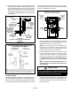
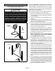
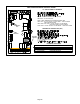
INTERIOR MAKE−UP BOX INSTALLATION
MAKE−UP
BOX
Right Side
FIGURE 49
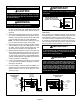
INTERIOR MAKE−UP BOX INSTALLATION
MAKE−UP
BOX
Left side
FIGURE 50
The unit is equipped with a field make−up box. The make−
up box may be moved to the right side of the furnace to fa-
cilitate installation. If the make−up box is moved to the right
side, the excess wire must be pulled into the blower
compartment. Secure the excess wire to the existing har-
ness to protect it from damage.
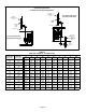
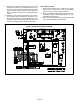
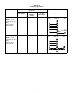
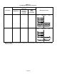
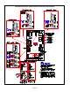
Refer to figure 51 and table 10 for field wiring and figure 54
for schematic wiring diagram and troubleshooting.
1 − Select circuit protection and wire size according to the
unit nameplate. The power supply wiring must meet
Class I restrictions.
2 − Holes are on both sides of the furnace cabinet to facili-
tate wiring.
3 − Install a separate disconnect switch (protected by ei-
ther fuse or circuit breaker) near the furnace so that
power can be turned off for servicing.
4 − Before connecting the thermostat or the power wiring,
check to make sure the wires will be long enough for
servicing at a later date. Remove the blower access
panel to check the length of the wire.
5 − Complete the wiring connections to the equipment.
Use the provided unit wiring diagram and the field wir-
ing diagram shown in figure 51 and table 10. Use
18−gauge wire or larger that is suitable for Class II rat-
ing for thermostat connections.
NOTE − Do NOT make a wire connection between
the room thermostat L terminal and the L terminal
of the G61MP integrated control.
6 − Electrically ground the unit according to local codes or,
in the absence of local codes, according to the current
National Electric Code (ANSI/NFPA No. 70) for the
USA and current Canadian Electric Code part 1 (CSA
standard C22.1) for Canada. A green ground wire is
provided in the field make−up box.
NOTE − The G61MP furnace contains electronic com-
ponents that are polarity sensitive. Make sure that the
furnace is wired correctly and is properly grounded.
7 − One line voltage HUM" 1/4" spade terminal is provided
on the furnace control board. Any humidifier rated up
to one amp can be connected to this terminal with the
neutral leg of the circuit being connected to one of the
provided neutral terminals. See figure 52 for control
board configuration. This terminal is energized in the
heating mode when the combustion air inducer is oper-
ating.
8 − One line voltage EAC" 1/4" spade terminal is provided
on the furnace control board. Any electronic air cleaner
rated up to one amp can be connected to this terminal
with the neutral leg of the circuit being connected to
one of the provided neutral terminals. See figure 52 for
control board configuration. This terminal is energized
when the indoor blower is operating.