
User's Manual


Page 3
CBX25UH SERIES
Requirements
WARNING
Excessive Weight Hazard - Use two or more people
when moving and installing the unit. Failure to do so can
result in back or other type of injury.
IMPORTANT
The CBX25UH units are designed to match, and must be
used with, outdoor units as rated. The indoor sections
are manufactured with a check/expansion valve (TXV)
to provide optimum refrigerant control and system
performance with a variety of different capacities of out
door units.
CAUTION
Physical contact with metal edges and corners while
applying excessive force or rapid motion can result in
personal injury. Be aware of, and use caution when
working near these areas during installation or while
servicing this equipment.
These instructions are intended as a general guide and do
not supersede local or national codes in any way. Consult
authorities having jurisdiction before installation.
Compliance with all local, state, or national codes
pertaining to this type of equipment should be determined
prior to installation. Read this instruction manual, as well
as the instructions supplied in separate equipment, before
starting the installation.
In addition to conforming to manufacturer's installation
instructions and local municipal building codes, installation
of Lennox air handler units (with or without optional electric
heat), MUST conform with National Fire Protection
Association (NFPA) standards: “Standard for Installation
of Air Conditioning and Ventilation Systems” (NFPA No.
90A) and “Standard for Installation of Residence Type
Warm Air Heating and Air Conditioning Systems” (NFPA
No. 90B).
All models are designed for indoor installation only. The
installation of the air handler, field wiring, duct system, etc.
must conform to the requirements of the National Electrical
Code, ANSI/NFPA No. 70 (latest edition) in the United
States, and any state laws, and local ordinances (including
plumbing or wastewater codes). Local authorities having
jurisdiction should be consulted before installation is
made. Such applicable regulations or requirements take
precedence over the general instructions in this manual.
Install the conditioned air plenum, ducts and air filters
(provided) in accordance with NFPA 90B Standard for the
Installation of Warm Air Heating and Air-Conditioning
Systems (latest edition).
The air handler is shipped from the factory completely
assembled. The unit is provided with flanges for the
connection of the duct system.
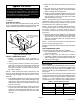
Do not remove the cabinet knockouts until it has been
determined which knockouts will need to be removed for
the installation.
Select the final air discharge position which best suits the
site conditions. Consider required clearances, space,
routing requirements for refrigerant line, condensate
disposal, filters, duct system, wiring, and accessibility for
service. Refer to the air handler rating plate on the air
handler for specific information.
WARNING
Danger of explosion. Keep flammable ma
terials and vapors, such as gasoline, away
from air handler. Place air handler so that
heating elements are at least 18 inches (46
cm) above the floor for a garage installa
tion. Failure to follow these instructions
can result in death, explosion, or fire.
NOTES —
During cooling operation, excessive sweating may occur if
the air handler is installed in a warm and humid space.
If installed in an unconditioned space, sealant should be
applied around the electrical wires, refrigerant tubing, and
condensate lines where they enter the cabinet.
Electrical wires should be sealed on the inside where they
exit the conduit opening. Sealant is required to prevent air
leakage into, and condensate from forming inside of, the
air handler, the control box, and on the electrical controls.
This unit is approved for installation clearance to
combustible material as stated on the unit rating plate.
Accessibility and service clearances must take
precedence over combustible material clearances.
The air handler must be installed so that free access is
allowed to the coil/filter compartment and blower/control
compartment.
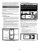
Installation Clearances
NON-DUCTED RETURN CLOSET INSTALLATION
The air handler can be installed in a closet with a false
bottom to form a return air plenum. It may also be installed
with a return air plenum under the air handler.
Louvers or return air grilles are field‐supplied. Local codes
may limit application of systems without a ducted return to
single story buildings.
When a CBX25UH unit is installed in a closet with a
louvered return opening, the minimum open area for the
louvers will be:
S 320 square inches for -018 and -024 models;
S 360 square inches for -030 and -036 models;
S 450 square inches for -042 thru -060 models.
If the free area is not known, assume a 25% free area for
wood or a 75% free area for metal louvers or grilles. Using
the louver dimensions and the 25% or 75% assumption,
determine if the open area meets the minimum open area
listed above.