
User's Manual


Page 7
CBX25UH SERIES
IMPORTANT
A field-fabricated secondary drain pan, with a drain pipe
to the outside of the building, is required in all installa
tions over a finished living space or in any area that may
be damaged by overflow from the main drain pan. In
some localities, local codes may require a secondary
drain pan for any horizontal installation.
The air handler is provided with ¾” NPT condensate drain
connections.
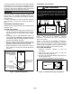
SLOPING THE DRAIN
Make sure the unit is sloped (similar to the slope shown in
figure 10) (horizontal or upflow) so that the drain pan will
empty completely without water standing in the pan.
THIS CORNER SHOULD BE 5/8” (+/- 1/8”) HIGHER
THAN DRAIN CORNER
DRAIN CORNER
THIS CORNER SHOULD BE
5/8” (+/- 1/8”) HIGHER THAN
DRAIN CORNER
Figure 10. Sloping the Drain
INSTALL CONDENSATE DRAIN
1. Remove the appropriate drain knockouts. If
necessary, remove the indoor coil assembly from the
cabinet.
2. Connect primary drain line connection to the primary
drain pan connection. The primary drain connection is
flush with the bottom of the inside of the pan.
Secondary connection is raised above the bottom of
the inside of the pan.
NOTE — When making drain fitting connections to the
drain pan, hand tighten the fitting and use a thread sealant.
Over-tightening the fittings can split connections on the
drain pan.
3. If the auxiliary drain line is to be used, remove the plug
and route the drain line so that water draining from the
outlet will be easily noticed by the homeowner. The
auxiliary drain line does not require venting or a trap.
Refer to local codes.
4. After removal of drain pan plugs, check the drain port
to see if holes have been drilled. If not drilled, use a
19/32” bit to drill out the primary drain hole; use a 3/8”
drill bit for the secondary drain hole. Remove all drill
shavings.
5. Make sure drain ports and drain pan are free of all
debris.
6. Plug and check any unused drain pan openings for
tightness. Torque plugs to 30 in. lb. to prevent water
leaks or seepage from the drain pan.
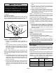
7. Install a 2” trap in the primary drain lines as close to the
unit as practical (see figure 9). Make sure the top of the
trap is below the connection to the drain pan to allow
complete drainage of the pan.
NOTE — Horizontal runs must have an anti-siphon air vent
(standpipe) installed ahead of the horizontal run (See
figure 9). An extremely long horizontal run may require an
oversized drain line to eliminate air trapping.
NOTE — Do not operate air handler without a drain trap.
The condensate drain is on the negative pressure side of
the blower; therefore, air being pulled through the
condensate line will prevent positive drainage without a
proper trap.
8. Route the drain line to the outside or to an appropriate
drain. Drain lines must be installed so they do not block
service access to the front of the air handler. A 24”
clearance is required for filter, coil, or blower removal
and service access.
NOTE — Check local codes before connecting the drain
line to an existing drainage system.
Insulate the drain lines where sweating could cause water
damage.
TEST CONDENSATE DRAIN
Test the drain pan and drain line after installation:
1. Pour several quarts of water into drain pan, enough to
fill drain trap and line.
2. Check to make sure the drain pan is draining
completely, no leaks are found in drain line fittings, and
water is draining from the end of the primary drain line.
3. Correct any leaks found.
Duct System and Filters
DUCT SYSTEM
The air handler is provided with flanges for the connection
of the plenum and ducts. The air handler is equipped with
flanges that can form a filter rack for the installation of the
air filter, or the filter may be installed as part of the return air
duct system.
Supply and return duct system must be adequately sized
to meet the system's air requirements and static pressure
capabilities. The duct system should be insulated with a
minimum of 1” thick insulation with a vapor barrier in
conditioned areas or 2” minimum in unconditioned areas.
Table 1. Unit Air Filter Size Chart
Model Filter Size Actual Minimum
Filter Size
-018 12” x 20” x 1 11.50” x 19.50” x .75”
-024 and -030 15” x 20” x 1 14.50” x 19.50” x .75”
-036 18” x 20” x 1 17.50” x 19.50” x .75”
-042, -048 and -060 18” x 24” x 1 17.50” x 23.50” x .75”