INSTALLATION INSTRUCTIONS SLP98DFV 2011 Lennox Industries Inc. Dallas, Texas, USA DAVE LENNOX SIGNATURE® COLLECTION GAS FURNACE DOWNFLOW AIR DISCHARGE 506611−01 02/2011 Supersedes 10/2010 Litho U.S.A. THIS MANUAL MUST BE LEFT WITH THE HOMEOWNER FOR FUTURE REFERENCE This is a safety alert symbol and should never be ignored. When you see this symbol on labels or in manuals, be alert to the potential for personal injury or death.
Unit Dimensions − inches (mm) 9/16 (14) COMBUSTION AIR INTAKE RETURN AIR OPENING B EXHAUST AIR OUTLET 2−1/16 (52) 5 (127) 27−3/4 (7705) 9/16 (14) B AIR TOP VIEW 1−1/2 (38) Front Panel A 19−7/16 (494) ELECTRICAL INLET (Either Side) 2 (51) Either Side CONDENSATE TRAP CONNECTION (Either Side) GAS PIPING INLET (Either Side) 9−1/8 (232) Right 6−9/16 (167) Left C 9/16 (14) FLOW 33 (838) 3/4 (19) 9/16 (14) 2−1/4 (57) Supply Air 6−7/16 (163) Either Side 19−1/4 Supply (489) Air 3/4 (19) FR
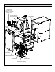
Parts Arrangement CONTROL BOX (includes variable capacity integrated control, transformer, circuit breaker and door switch) BLOWER ASSEMBLY (Variable Speed Blower Motor Is Hidden) BAG ASSEMBLY BLOWER ACCESS PANEL ACCESS PANEL COMBUSTION AIR INDUCER GAS VALVE PRIMARY LIMIT BURNER BOX ASSEMBLY FIGURE 1 Page 3
SLP98DFV Gas Furnace Safety Information The SLP98DFV category IV gas furnace is equipped with a variable−capacity, variable−speed integrated control. This control ensures compatibility with the Lennox icomfort Touch thermostat and Harmony III zone control system, as well as a thermostat which provides humidity control. The furnace is equipped for installation in natural gas applications only. A changeover kit may be ordered for LP applications.
Installed in Combination with a Cooling Coil When this furnace is used with cooling units, it shall be installed in parallel with, or on the upstream side of, cooling units to avoid condensation in the heating compartment. With a parallel flow arrangement, a damper (or other means to control the flow of air) must adequately prevent chilled air from entering the furnace (figure 3).
• When the furnace is installed in an unconditioned space, consider provisions required to prevent freezing of condensate drain system. General WARNING Installation − Setting Equipment Product contains fiberglass wool. Disturbing the insulation in this product during installation, maintenance, or repair will expose you to fiberglass wool. Breathing this may cause lung cancer. (Fiberglass wool is known to the State of California to cause cancer.
NOTE − The 1/2 hp blower motor used in some SLP98DFV unit is equipped with three flexible legs and one rigid leg. The rigid leg is equipped with a shipping bolt and a flat white plastic washer (rather than the rubber mounting grommet used with a flexible mounting leg). The bolt and washer must be removed before the furnace is placed into operation. After the bolt and washer have been removed, the rigid leg will not touch the blower housing.
TABLE 1 NON−COMBUSTIBLE FLOOR OPENING SIZE Front to Rear Cabinet Width SLP98DF UNIT Side to Side in. mm in. mm B Cabinet (17.5") 19 − 3/4 502 16 − 5/8 422 C Cabinet (21") 19 − 3/4 502 20−1/8 511 SUPPLY AIR PLENUM PROPERLY SIZED FLOOR OPENING NOTE − Floor opening dimensions listed are 1/4 inch (6 mm) larger than the unit opening. See dimension drawing on page 2.
PLENUM (Field Provided) SLP98DF UNIT SECURE FROM INSIDE CABINET COOLING COIL PROPERLY SIZED FLOOR OPENING ÉÉÉÉ SEALING STRIP (Field Provided) CABINET SIDE PANEL Side View FIGURE 12 PLENUM Filters This unit is not equipped with a filter or rack. A field−provided filter is required for the unit to operate properly. Table 3 lists recommended filter size. A filter must be in place whenever the unit is operating.
Pipe & Fittings Specifications All pipe, fittings, primer and solvent cement must conform with American National Standard Institute and the American Society for Testing and Materials (ANSI/ASTM) standards. The solvent shall be free−flowing and contain no lumps, undissolved particles or any foreign matter that adversely affects the joint strength or chemical resistance of the cement. The cement shall show no gelation, stratification, or separation that cannot be removed by stirring.
TABLE 5 OUTDOOR TERMINATION KITS USAGE STANDARD SLP98DF UNIT 070 090 110 VENT PIPE DIA. (in.) CONCENTRIC Outdoor Exhaust Accelerator (Dia. X Length) Outdoor Exhaust Accelerator (Dia.
1 − In areas where piping penetrates joists or interior walls, hole must be large enough to allow clearance on all sides of pipe through center of hole using a hanger. Venting Practices Piping Suspension Guidelines SCHEDULE 40 PVC −− Support every 5 feet. all other pipe* −− Support every 3 feet. 2 − When furnace is installed in a residence where unit is shut down for an extended period of time, such as a vacation home, make provisions for draining condensate collection trap and lines.
NOTE − The exhaust collar on all models is sized to accommodate 2" Schedule 40 vent pipe. Contact the Application Department for more information concerning sizing of vent systems which include multiple pipe sizes. 1 Furnace Capacity? 070, 090, 110 btuh NOTE − All horizontal runs of exhaust pipe must slope back toward unit. A minimum of 1/4" (6mm) drop for each 12" (305mm) of horizontal run is mandatory for drainage. NOTE − Exhaust pipe MUST be glued to furnace exhaust fittings.
TABLE 7 Maximum Allowable Intake or Exhaust Vent Length in Feet *Size intake and exhaust pipe length separately. Values in table are for Intake OR Exhaust, not combined total. Both Intake and Exhaust must be same pipe size.
TABLE 7 Maximum Allowable Intake or Exhaust Vent Length in Feet *Size intake and exhaust pipe length separately. Values in table are for Intake OR Exhaust, not combined total. Both Intake and Exhaust must be same pipe size.
TYPICAL EXHAUST PIPE CONNECTIONS AND CONDENSATE TRAP INSTALLATION 2” 2” 2” DO NOT transition from smaller to larger pipe size in horizontal runs of exhaust pipe. 3” TRANSITION TRAP *2“ Use only the factory−supplied trap. Trap can be installed on either side of cabinet within 5 ft. of the furnace. Air Intake Exhaust TOP VIEW * When transitioning up in pipe size, use the shortest length of 2” PVC pipe possible. NOTE − Exhaust pipe and intake pipe must be the same diameter.
VENT TERMINATION CLEARANCES FOR DIRECT VENT INSTALLATIONS IN THE USA AND CANADA INSIDE CORNER DETAIL G H A D E B L Fixed Closed Operable F B B C I Fixed Closed Operable M B K J A B VENT TERMINAL A= Clearance above grade, veranda, porch, deck or balcony B= Clearance to window or door that may be opened C= Clearance to permanently closed window D= Vertical clearance to ventilated soffit located above the terminal within a horizontal distance of 2 feet (mm) from the center line of the
Details of Intake and Exhaust Piping Terminations for Direct Vent Installations NOTE − In Direct Vent installations, combustion air is taken from outdoors and flue gases are discharged to outdoors. NOTE − Flue gas may be slightly acidic and may adversely affect some building materials. If any vent termination is used and the flue gasses may impinge on the building material, a corrosion−resistant shield (minimum 24 inches square) should be used to protect the wall surface.
B B D D C Intake C 3 1 Front View of Intake and Exhaust A Exhaust A 2 Intake Exhaust TABLE 8 D 1 E B 12" C 2 A 2" (51mm) Vent Pipe A− Clearance above grade or average snow accumulation B−Horizontal separation between intake and exhaust C−Minimum from end of exhaust to inlet of intake D−Exhaust pipe length E−Wall support distance from top of each pipe (intake/exhaust) 12" (508MM) Min. 3" (76mm) Vent Pipe 12" (508MM) Min. 6" (152MM) Min. 6" (152MM) Min.
TABLE 9 FIELD−SUPPLIED WALL TERMINATION OR (15F74) WALL RING TERMINATION KIT With INTAKE ELBOW NOTE − FIELD−PROVIDED REDUCER MAY BE REQUIRED TO ADAPT LARGER VENT PIPE SIZE TO TERMINATION. 1/2" (13mm) ARMAFLEX INSULATION IN UNCONDITIONED SPACE SIZE TERMINATION PER TABLE 9 D B C A STRAIGHT APPPLICATION 1/2" (13mm) ARMAFLEX INSULATION IN UNCONDITIONED SPACE D E * WALL SUPPORT B A EXTENDED APPLICATION C See venting table 7 for maximum venting lengths with this arrangement.
FIELD−PROVIDED REDUCER MAY BE REQUIRED TO ADAPT LARGER VENT PIPE SIZE TO TERMINATION. 1−1/2" (38mm) accelerator provided on 71M80 & 44W92 kits for SL98DF070V36B EXHAUST AIR SIZE TERMINATION PIPE PER TABLE 9. INTAKE AIR INTAKE AIR OUTSIDE WALL EXHAUST VENT Front View EXHAUST AIR Top View INTAKE AIR 1/2" (13mm) Foam Insulation in Unconditioned Space 12" (305mm) Min. INTAKE above grade or AIR average snow accumulation.
WALL TERMINATION KITS (CLOSE−COUPLE) EXTENDED VENT FOR GRADE CLEARANCE 2 inch (51 mm) 22G44 (US) 3 inch (76 mm) 44J40 (US) If intake and exhaust pipe is less than 12 in. (305 mm) above snow accumulation or other obstructions, field−fabricated piping must be installed. WALL SUPPORT* FIELD−PROVIDED REDUCER MAY BE REQUIRED TO ADAPT LARGER VENT PIPE SIZE TO TERMINATION 8” (203 mm) min. for 2” (51 mm) & 3” (76 mm) dia. pipe between the end of the exhaust pipe and intake pipe. 12” (305 mm) max.
Condensate Piping This unit is designed for either right- or left-side exit of condensate piping. Refer to figure 32 for condensate trap locations. NOTE − If necessary the condensate trap may be installed up to 5 feet away from the furnace. Piping from furnace must slope down a minimum of 1/4" per ft. toward trap. NOTE − Vinyl tubing may be used for condensate drain. Tubing must be 1−1/4" OD X 1" ID and should be attached to the drain on the trap using a hose clamp.
TRAP / DRAIN ASSEMBLY USING 1/2" PVC OR 3/4" PVC OPTIONAL Condensate Drain Connection Adapter 1/2 inch slip X 1/2 inch mpt (Not Furnished) Adapter 1/2 inch slip X 1/2 inch mpt (Not Furnished) 90° Street Elbow 1/2 inch PVC (Not Furnished) 1 (25) Minimum Vent 5 Feet Maximum Above Top of Condensate Drain Connection In Unit 90° Elbow 1/2 inch PVC (Not Furnished) Condensate Drain Connection In Unit OPTIONAL Drain Piping 1/2 inch PVC Pipe (Not Furnished) 1/2 inch PVC Pipe (Not Furnished) Coupling 1/2 inch
CAUTION A separate drain line must be run to the drain from the condensate trap to ensure proper drainage and pressure switch operation. DO NOT connect the condensate trap drain into the drain line from the evaporator coil. SL98DFV with Evaporator Coil Condensate trap and evaporator coil must drain separately as shown. Field−Provided Vent 4 − Piping should be sloped 1/4 inch per 15 feet (6mm per 5.6m) upward toward the gas meter from the furnace.
Left Side Piping (Standard) MANUAL MAIN SHUT−OFF VALVE (1/8 in. NPT plugged tap shown) AUTOMATIC GAS VALVE (with manual shut−off valve) AUTOMATIC GAS VALVE (with manual shut−off valve) MANUAL MAIN SHUT−OFF VALVE (1/8 in.
1 − Seal any unused openings in the common venting system. INTERIOR MAKE−UP BOX 2 − Inspect the venting system for proper size and horizontal pitch. Determine that there is no blockage, restriction, leakage, corrosion, or other deficiencies which could cause an unsafe condition. (FACTORY− INSTALLED LEFT SIDE) 3 − Close all building doors and windows and all doors between the space in which the appliances remaining connected to the common venting system are located and other spaces of the building.
1 − The power supply wiring must meet Class I restrictions. Protected by either a fuse or circuit breaker, select circuit protection and wire size according to unit nameplate. NOTE − Unit nameplate states maximum current draw. See table for maximum over−current protection. TABLE 11 SLP98DF Model Maximum Over−Current Protection (Amps) 07036B, 09036C, 09048C 15 09060C, 11060C 20 2 − Holes are on both sides of the furnace cabinet to facilitate wiring.
1 − When the thermostat is set to FAN ON," the indoor blower will run continuously at a percentage of the second−stage cooling speed when there is no cooling or heating demand. The percentage is set using DIP switches 6 and 7. 2 − When the SLP98DFV is running in the heating mode, the integrated control will automatically adjust the blower speed to match the furnace firing rate. This speed can be adjusted up or down by 7.
icomfort Touch Thermostat with SLP98DFV and Non−Communicating Outdoor Unit icomfort Touch Thermostat with SLP98DFV and icomfort −ENABLED Outdoor Unit icomfort Touch Thermostat icomfort −Enabled SLP98DFV Indoor Furnace Non−Communicating Outdoor Air Conditioner OPTIONAL DISCHARGE AIR SENSOR icomfort Touch THERMOSTAT icomfort Touch Thermostat icomfort −Enabled SLP98DFV Indoor Furnace icomfort −Enabled Outdoor Air Conditioner or Heat Pump icomfort − ENABLED SLP98DFV FURNACE icomfort − ENABLED SLP98D
Optional Accessories for use with any icomfort Touch System icomfort − ENABLED SLP98DFV FURNACE NOTE: icomfort THERMOSTAT SENSES HUMIDITY & CONTROLS 24V H" OUTPUT (& 120V H" OUTPUT) TO CYCLE HUMIDIFIER BASED ON DEMAND. NO OTHER CONTROL OR HUMIDISTAT REQUIRED. OPTIONAL OUTDOOR AIR SENSOR FOR USE WITH HUMIDIFIER (IF NOT ALREADY IN THE SYSTEM FOR OTHER FUNCTIONS. BUILT INTO ALL icomfort OUTDOOR UNITS).
TABLE 14 Field Wiring Connections for Non−Communicating Thermostat Applications Thermostat DIP Switch Settings and On−Board Links (figure 44) W914 W915 (DS to R) W951 Dehumidifi(Y1 to Y2) DIP Switch 1 (O to R) Two−Stage cation or Heat Pumps Harmony Cooling III 1Heat / 1 Cool NOTE − Use DIP switch 3 to set second−stage heat ON delay. OFF−7 minutes. ON−12 minutes. ON 1 Heat / 2 Cool NOTE − Use DIP switch 3 to set second−stage heat ON delay. OFF−7 minutes. ON−12 minutes.
TABLE 14 Field Wiring for Non−Communicating Applications (Continued) Thermostat 2 Heat / 2 Cool DIP Switch Settings and On−Board Links (figure 44) W914 W915 (DS to R) (Y1 to Y2) W951 DehumidifiTwo−Stage DIP Switch 1 (O to R) cation or Cooling Heat Pumps Harmony III OFF Cut Intact Intact Wiring Connections S1 T’STAT CONTROL TERM. STRIP OUTDOOR UNIT * 2 Heat / 2 Cool with t’stat with dehumidification mode OFF Cut Cut Intact S1 T’STAT CONTROL OUTDOOR TERM.
TABLE 14 Field Wiring for Non−Communicating Applications (Continued) Thermostat Dual Fuel Single−Stage Heat Pump DIP Switch Settings and On−Board Links (figure 44) W914 W915 (DS to R) W951 (Y1 to Y2) DehumidifiDIP Switch (O to R) Two−Stage cation or Heat Pumps Cooling Harmony III DIP Switch 1 OFF Intact Intact Cut Wiring Connections L7724U T’STAT CONTROL TERM.
TYPICAL SLP98DFV WIRING DIAGRAM FIGURE 43 Page 35
Integrated Control INTEGRATED CONTROL NEUTRAL TERMINALS COMBUSTION AIR INDUCER CONNECTOR IGNITOR CONNECTOR FLAME SENSE DIAGNOSTIC PUSH BUTTON LINE VOLTAGE TERMINALS + HUM DIP SWITCHES EAC OUTDOOR AIR SENSOR TERMINALS INDOOR BLOWER CONNECTOR 7−SEGMENT DIAGNOSTIC LED W915 Y1 TO Y2 W951 R TO O DISCHARGE AIR SENSOR TERMINALS FACTORY TEST HEADER PINS. FACTORY USE ONLY. W914 R TO DS W915 W951 W914 TB83 OUTDOOR L − use only with communicating T’stat and non−communicating outdoor unit.
TABLE 15 Non−Communicating Thermostat Selection Switch Settings Operation Thermostat Switch 1 Switch 2 Switch 3 Variable Capacity Heat (35% to 100%) Two−Stage Off On Off Three−Stage Heat (35%, 70%, 100%) Single−Stage On Off 2nd stage delay OFF = 7 minutes ON = 12 minutes 3rd stage delay 10 minutes fixed Two−Stage Heat (W1 70%, W2 100%) Two−Stage Off Off Off NOTE − When the SLP98DFV is used with an icomfort Toucht communicating thermostat, all indoor blower speed selections and DIP switch
Switches 8 and 9 −− Cooling Mode Blower Speed −− The unit is shipped from the factory with the DIP switches positioned for high speed (4) indoor blower motor operation during the cooling mode. The table below provides the cooling mode blower speeds that will result from different switch settings. Refer to tables beginning on page 37 for corresponding cfm values.
Switches 14 through 19 −− Heating Mode Blower Speed −− These switches are factory set at the OFF position which provides 100 % of normal speed during HIGH HEAT demand, 70% of normal speed during MID−RANGE HEAT demand and 35% of normal speed during LOW HEAT demand. Switches 14, 15 and 16 are used to adjust the LOW HEAT blower motor speed. Switches 17, 18 and 19 are used to adjust the HIGH HEAT blower motor speed.
BLOWER DATA SLP98DF070V36B BLOWER PERFORMANCE (less filter) HEATING BLOWER PERFORMANCE Heating Adjust CFM Selections Heating Input Range and Blower Volume - CFM 35% 40% 50% 60% 70% 80% 90% 100% Increase (+15%) Heat CFM 495 543 639 735 830 926 1022 1118 Increase (+7.5%) Heat CFM 473 516 604 691 778 866 953 1041 Default Heat CFM 450 489 568 647 726 805 884 963 Decrease (-7.
BLOWER DATA SLP98DF090V48C BLOWER PERFORMANCE (less filter) HEATING BLOWER PERFORMANCE Heating Adjust CFM Selections Heating Input Range and Blower Volume - CFM 35% 40% 50% 60% 70% 80% 90% 100% Increase (+15%) Heat CFM 723 790 925 1060 1195 1329 1464 1599 Increase (+7.5%) Heat CFM 690 752 878 1004 1129 1255 1381 1507 Default Heat CFM 656 714 831 948 1064 1181 1297 1414 Decrease (-7.
BLOWER DATA SLP98DF110V60C BLOWER PERFORMANCE (less filter) HEATING BLOWER PERFORMANCE Heating Adjust CFM Selections Heating Input Range and Blower Volume - CFM 35% 40% 50% 60% 70% 80% 90% 100% Increase (+15%) Heat CFM 811 906 1096 1286 1475 1665 1855 2045 Increase (+7.5%) Heat CFM 744 835 1017 1199 1380 1562 1744 1926 Default Heat CFM 677 764 938 1112 1285 1459 1633 1807 Decrease (-7.
TABLE 24 COOLING OPERATING SEQUENCE SLP98DFV and Single−Stage Outdoor Unit OPERATING SEQUENCE SYSTEM DEMAND Demand System Condition Step 1st stage SYSTEM RESPONSE Relative Humidity Compressor Blower CFM (COOL) O G Status D* On On Acceptable 24 VAC High 100% Comments NO CALL FOR DEHUMIDIFICATION Normal Operation 1 On Compressor and indoor blower follow thermostat demand BASIC MODE (only active on a Y1 thermostat demand) Normal Operation 1 On On On Acceptable 24 VAC High 100% D
TABLE 25 COOLING OPERATING SEQUENCE SLP98DFV and Two−Stage Outdoor Unit OPERATING SEQUENCE SYSTEM DEMAND Demand System Condition Step 1st stage 2nd stage SYSTEM RESPONSE Relative Humidity Compressor Blower CFM (COOL) O G Status D* On On Acceptable 24 VAC Low 70% On On Acceptable 24 VAC High 100% Comments NO CALL FOR DEHUMIDIFICATION Normal Operation − Y1 1 On Normal Operation − Y2 2 On On Compressor and indoor blower follow thermostat demand ROOM THERMOSTAT CALLS FOR FIRST
Unit Start−Up FOR YOUR SAFETY READ BEFORE OPERATING WARNING Do not use this furnace if any part has been underwater. A flood−damaged furnace is extremely dangerous. Attempts to use the furnace can result in fire or explosion. Immediately call a qualified service technician to inspect the furnace and to replace all gas controls, control system parts, and electrical parts that have been wet or to replace the furnace, if deemed necessary. WARNING Danger of explosion.
9 − Replace the access panel. SLP98DFV units require no manifold pressure adjustments for operation at altitudes up to 10,000 feet (3048 m) above sea level. Units installed at altitude of 7,501 to 10,000 feet (2287 to 3048m) require a pressure switch change per table 27. Table 27 lists conversion kit requirements and manifold pressures at all altitudes. The combustion air pressure switch is factory−set and requires no adjustment.
Proper Combustion Other Unit Adjustments Furnace should operate minimum 15 minutes with correct manifold pressure and gas flow rate before checking combustion. Take combustion sample beyond the flue outlet and compare to the tables below. The maximum carbon monoxide reading should not exceed 50 ppm. SLP98DFV Unit TABLE 28 High Fire CO2% For Nat CO2% For L.P. 070V36B 090V36C 090V60C 7.6 − 8.6 9,1 − 10.
Temperature Rise After the furnace has been started and supply and return air temperatures have been allowed to stabilize, check the temperature rise with the unit operating at 100 percent firing rate. If necessary, adjust the blower speed to maintain the temperature rise within the range shown on the unit nameplate. Increase the blower speed to decrease the temperature. Decrease the blower speed to increase the temperature rise. Failure to adjust the temperature rise may cause erratic limit operation.
2− 3− 4− 5− 6− 7− 8− closed contacts and pressure switches for normally open contacts. The combustion air inducer is energized at ignition speed, which is approximately the same as the inducer speed at 70 percent firing rate. Once the control receives a signal that the low−fire pressure switch has closed, the combustion air inducer begins a 15−second pre−purge in low speed. After the pre−purge is complete, a 20−second initial ignitor warm−up period begins.
Service WARNING ELECTRICAL SHOCK, FIRE, OR EXPLOSION HAZARD. Failure to follow safety warnings exactly could result in dangerous operation, serious injury, death or property damage. Improper servicing could result in dangerous operation, serious injury, death, or property damage. Before servicing, disconnect all electrical power to furnace. When servicing controls, label all wires prior to disconnecting. Take care to reconnect wires correctly. Verify proper operation after servicing.
19 − Thoroughly rinse and drain the heat exchanger. Soap solutions can be corrosive. Take care to rinse entire assembly. 20 − Reinstall heat exchanger into cabinet making sure that the clamshells of the heat exchanger assembly are resting on the support located at the rear of the cabinet. Remove the indoor blower to view this area through the blower opening. 21 − Re-secure the supporting screws along the vestibule sides and top to the cabinet. 22 − Reinstall cabinet screws on front flange at blower deck.
Planned Service A service technician should check the following items during an annual inspection. Power to the unit must be shut off for the service technician’s safety. Burners − Must be inspected for rust, dirt, or signs of water. Return air duct − Must be properly attached and provide an air seal to the unit. Operating performance − Unit must be observed during operation to monitor proper performance of the unit and the vent system.
Integrated Control Diagnostic Codes Press the diagnostic push button and hold it to cycle through a menu of options. Every five seconds a new menu item will be displayed. Release the button when the desired mode is displayed. When a solid "P" is displayed, the furnace capacity/ size is programmed. When the solid E" is displayed, the control enters the Error Code Recall mode.
Integrated Control Diagnostic Codes (continued) Code Diagnostic Codes/Status of Equipment Action Required to Clear and Recover E 223 Low pressure switch failed open − Refer to troubleshooting in installation instruction. Check inches of water column pressure during operation of low pressure switch on heat call, measure inches of water column of operating pressure, inspect vent and combustion air inducer for correct operation and restriction.
Integrated Control Diagnostic Codes (continued) Code Diagnostic Codes/Status of Equipment Action Required to Clear and Recover E 295 Indoor blower motor temperature is too high. Indoor blower motor over temperature (motor tripped on internal protector), Check motor bearings, amperes. Replace if necessary. E 310 Discharge error sensor failure − No error if disconnected. Only shown if shorted or out−of−range. Discharge air temperature(DATS) out of range, code is activated during "Field test mode".
Configuring Unit Size Code Power−Up − Number displayed represents by integrated control unit size code (furnace model and capacity). If three horizontal bars are displayed followed by continuous E203, furnace control does not recognize unit size code. Configure per the following: Furnace control in IDLE mode No heating, cooling or indoor fan operation) Yes To enter Field Test Mode: push and hold button next to 7−segment LED display until solid dash symbol appears. Release button.
Troubleshooting: Heating Sequence of Operation IGNITION AND CALL FOR LOW FIRE WITH TWO−STAGE THERMOSTAT 1 Safety Check Verify There Is No Main Burner Flame Limit Switch Closed? Indoor blower OFF After Heat OFF Delay (Low Heat Speed) NO De−Energize Gas Valve Combustion Air Inducer On (100% rate speed) YES Indoor Blower ON (100%) Error Code Flashes Limit Closes Within 3 Minutes? Indoor Blower OFF After Heat OFF Delay (High Heat Speed) YES Rollout Circuit Closed? L I G H T NO De−Energize Gas Val
Troubleshooting: Heating Sequence of Operation (Continued) CALL FOR HIGH FIRE WITH TWO−STAGE THERMOSTAT 2 1 2 Stage Thermostat 1st Call for High Fire? YES NO 2nd Stage Recognition Delay (30 Seconds) Combustion Air Inducer ON (100% Rate Speed) High Pressure Switch Closes Within 10 Seconds? NO Increase Combustion Air Inducer Speed if Not at 100% Rate Speed Error Code Flashes YES Adjust Indoor Blower to Appropiate speed 3A Wait for Call for Heat Satisfied 1 System will always light at 70% even
Troubleshooting: Heating Sequence of Operation (Continued) CALL FOR HEAT SATISFIED RUN MODE (TWO−STAGE THERMOSTAT) FIRST OR SECOND−STAGE CALL FOR HEAT ALL INPUTS MONITORED (LIMIT, PRESSURE, CALL FOR HEAT/COOL, FLAME LEVEL).
Troubleshooting: Heating Sequence of Operation (Continued) 4 IGNITION AND CALL FOR HEAT WITH SINGLE−STAGE THERMOSTAT Safety Check Verify There Is No Main Burner Flame Limit Switch Closed? Indoor Blower OFF After Heat OFF Delay (Low Heat Speed) De−Energize Gas Valve NO Indoor Blower ON (100% Speed) Error Code Flashes Combustion Air Inducer ON (100%) YES Limit NO Closes Within 3 Minutes? Indoor Blower OFF After Heat OFF Delay (High Heat Speed) YES Rollout Circuit Closed? L I G H T O F F De−Energiz
Troubleshooting: Cooling Sequence of Operation CALL FOR COOLING 5 1st Stage Cooling Request Received 1 Energize 1st Stage Cooling Contactor (Compressor & Fan) Indoor Blower On After 2−second delay Energize Indoor Blower (Per Ramping Profile) 2 YES 1 2nd Stage Cooling Request? YES 1st Stage Cooling Request Still Active? NO YES Energize 2nd Stage Cooling Contactor (Compressor & Fan) Energize Indoor Blower (High Cooling mode) 2nd Stage Cooling Request Still Active? 2 YES Maintain Indoor Blower
Troubleshooting: Continuous Fan Sequence of Operation CONTINUOUS LOW SPEED INDOOR BLOWER SEQUENCE OF OPERATION 6 Call for Continuous Blower Indoor Blower On (Speed Determined by Dip Switch settings) Request for Cooling Received? Maintain Indoor Blower at set speed YES 5 Go to Call for Cooling 1 Go to Call for Heat −− Two−Stage Thermostat NO Request for Heat Received? Maintain Indoor Blower at set speed YES OR 4 NO Call for Fan Removed? NO Go to Call for Heat −− Single−Stage Thermostat Ma
Repair Parts List The following repair parts are available through Lennox dealers. When ordering parts, include the complete furnace model number listed on the nameplate −− Example: SLP98DF070V36B. All service must be performed by a licensed professional installer (or equivalent), service agency, or gas supplier.
Requirements for Commonwealth of Massachusetts Modifications to NFPA−54, Chapter 10 Revise NFPA−54 section 10.8.