
User's Manual


Page 46
9 − Replace the access panel.
10− Turn on all electrical power to to the unit.
11− Set the thermostat to desired setting.
NOTE − When unit is initially started, steps 1 through 11
may need to be repeated to purge air from gas line.
12− If the appliance will not operate, follow the instructions
Turning Off Gas to Unit" and call the gas supplier.
Turning Off Gas to Unit
1 − Set the thermostat to the lowest setting.
2 − Turn off all electrical power to the unit if service is to be
performed.
3 − Remove the access panel.
4 − Move the gas valve switch to the OFF position.
5 − Replace the access panel.
Failure To Operate
If the unit fails to operate, check the following:
1 − Is the thermostat calling for heat?
2 − Are access panels securely in place?
3 − Is the main disconnect switch closed?
4 − Is there a blown fuse?
5 − Is the filter dirty or plugged? Dirty or plugged filters will
cause the limit control to shut the unit off.
6 − Is gas turned on at the meter?
7 − Is the manual main shut-off valve open?
8 − Is the gas valve turned on?
9 − Is the unit ignition system in lock out? If the unit locks out
again, inspect the unit for blockages.
10 − Is blower harness connected to ignition control? Fur-
nace will not operate unless harness is connected.
High Altitude Information
NOTE − In Canada, certification for installations at eleva-
tions over 4500 feet (1372 m) is the jurisdiction of local au-
thorities.
SLP98DFV units require no manifold pressure adjust-
ments for operation at altitudes up to 10,000 feet (3048 m)
above sea level. Units installed at altitude of 7,501 to
10,000 feet (2287 to 3048m) require a pressure switch
change per table 27. Table 27 lists conversion kit require-
ments and manifold pressures at all altitudes.
The combustion air pressure switch is factory−set and re-
quires no adjustment.
NOTE − A natural to LP/propane gas changeover kit is nec-
essary to convert this unit. Refer to the changeover kit
installation instruction for the conversion procedure.
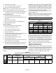
Gas Pressure Measurement
Gas Flow (Approximate)
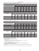
TABLE 26
GAS METER CLOCKING CHART
SLP98
Unit
Seconds for One Revolution
Natural LP
1 cu ft
Dial
2 cu ft
Dial
1 cu ft
Dial
2 cu ft
DIAL
−070 55 110 136 272
−090 41 82 102 204
−110 33 66 82 164
−135 27 54 68 136
Natural−1000 btu/cu ft LP−2500 btu/cu ft
Furnace should operate at least 5 minutes before check-
ing gas flow. Determine time in seconds for two revolu-
tions of gas through the meter. (Two revolutions assures a
more accurate time.) Divide by two and compare to time
in table 26 below. If manifold pressure matches table 27
and rate is incorrect, check gas orifices for proper size and
restriction. Remove temporary gas meter if installed.
NOTE − To obtain accurate reading, shut off all other gas
appliances connected to meter.
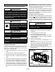
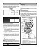
Supply Pressure Measurement
A threaded plug on the inlet side of the gas valve provides
access to the supply pressure tap. Remove the threaded
plug, install a field−provided barbed fitting and connect a
manometer to measure supply pressure. Replace the
threaded plug after measurements have been taken.
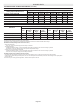
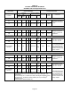
TABLE 27
Conversion Kit Requirements and Manifold Test Pressures
Model
Input
Size
LP/Propane
Kit
High Altitude Pressure
Switch Kit
Manifold Pressure at All Altitudes (in. w.g.)
Gas Orifice Size
0 − 10,000
(0 − 3048 m)
0 − 7,500
(0 − 2286 m)
7,501 − 10,000
(2287 −
3048m)
Low Fire
(35% rate)
High Fire
(100% rate)
Natural Gas LP/Propane Natural Gas LP/Propane Nat LP
−070
65W77 Not required 74W37 0.40 − 0.60 1.2 − 1.8 3.2 − 3.8 9.5 − 10.5 .0625 .034
−090
−110
NOTE − The values given in table 27 are measurements only. The gas valve should not be adjusted.