
User's Manual


Page 8
EQUIPMENT IN CONFINED SPACE
ALL AIR FROM OUTSIDE
(Inlet Air from Crawlspace and Outlet Air to Ventilated Attic)
NOTE−The inlet and outlet air openings shall each have a free area of at least one square inch (645
mm
2
) per 4,000 Btu (1.17 kW) per hour of the total input rating of all equipment in the enclosure.
VENTILATION LOUVERS
(Each end of attic)
OUTLET
AIR
WATER
HEATER
INLET
AIR
CHIMNEY OR
GAS VENT
FURNACE
VENTILATION
LOUVERS
(For unheated crawl space)
AIR FLOW
FIGURE 3
EQUIPMENT IN CONFINED SPACE
ALL AIR FROM OUTSIDE
(All Air Through Ventilated Attic)
NOTE−The inlet and outlet air openings shall each have a
free area of at least one square inch (645 mm
2
) per 4,000
Btu (1.17 kW) per hour of the total input rating of all equip-
ment in the enclosure.
CHIMNEY
OR GAS
VENT
WATER
HEATER
OUTLET
AIR
VENTILATION LOUVERS
(Each end of attic)
INLET AIR
(Ends 12 in.
above bottom)
FURNACE
AIR FLOW
FIGURE 4
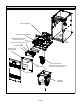
EQUIPMENT IN
CONFINED SPACE
ALL AIR FROM
OUTSIDE
OUTLET AIR
INLET AIR
WATER
HEATER
CHIMNEY
OR GAS
VENT
NOTE − Each air duct opening shall have a free area of at least
one square inch (645 mm
2
) per 2,000 Btu (.59 kW) per hour of
the total input rating of all equipment in the enclosure. If the
equipment room is located against an outside wall and the air
openings communicate directly with the outdoors, each open-
ing shall have a free area of at least one square inch (645 mm
2
)
per 4,000 Btu (1.17 kW) per hour of the total input rating of all
other equipment in the enclosure.
FURNACE
AIR FLOW
FIGURE 5