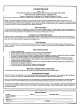
INSTALLATION AND MAINTENANCE INSTRUCTIONS PWC Series "Magic-Pak" Self-Contained Heat Pump [ WARNING Improper installation, adjustment, alteration, service or maintenance can cause injury or property damage. Refer to this manual. For assistance or additional information, consult a qualified installer or service agency. I _'WARNING I For your safety, do not store or use gasoline or other flammable vapors and liquids in the vicinity of this or any other appliance.
INSTALLATION the unit inside the carton if the carton is damaged. File a cfaim with the transportation company. If any damages are discovered and reported to the carrier DO NOT INSTALL THE UNIT, as claim may be denied. General =.se instructions explain the recommended method of ,llation of the PWC heat pump unit and associated e_uctricalwiring. Check the unit rating p'late to confirm specifications are as ordered.
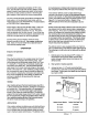
If the unit is installed in a residential garage, it must be located or protected to avoid physical damage by vehicles. The unit must be installed so that no electrical components are exposed to water. . Seal the space between the unit and building opening using a non-hardening caulking compound. The seal must be weathertight to prevent entrance of moisture and water into the building.
Application Limitations Outdoor Ambient Air Temperature Minimum DB - Cooling AirFilter All indoor return air must be filtered. A permanent-type filter is furnished with the unit, located directly behind the °F access panel. Removing the panel permits access to the filter.
Usewiringwitha temperature limitation of 75 =C minimum. Run the 208 or 230 volt, 60 hertz electric power supply through a fused disconnect switch to the control box of the unit and connect as shown in the wiring diagram located on the inside of the control access panel. is time/temperature initiated and temperature terminated with a maximum defrost time (time-out) of 10 minutes.
After closing test pins and appropriate cycle time has elapsed, the reversing valve should shift to defrost mode and the outdoor fan should stop. After 2 seconds of defrost operation, the reversing valve should shift back to ",tingoperation and the outdoor fan should start. Motors The indoor and outdoor fan motors are permanently lubricated and require no maintenance.
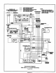
208/230-1-60 POWER SUPPLY WITHMIN. 75"CCOPPER WIRE I CIRCUIT1I •; ..; ........ .......... UNE VOLTAGE-FACTORY UNE VOLTAGE-RELD UNE VOLTAGE-RELD (IF USED) LOW VOLTAGE-FACTORY LOW VOLTAGE-FI ELD I (lo_cO_L'qCIRCUIT2 I : : NOTE: IF ANY OF THE ORIGINAL WIRES ARE REP_, THE SAME SIZE AND TYPE WIRE MUST BE USED.
208/230-1-60 :OWER SUPPLY WITH MIN. 75"C COPPER WIRE ..... ........ .......... I CIRCUIT 1 I :: i UNE LINE LINE LOW LOW VOLTAGE-FACTORY VOLTAGE-RELD VOLTAGE-FIELD (IF USED) VOLTAGE-FACTORY VOLTAGE-R ELD CIRCUIT 2 :• : RED F_ BLUE NOTE: IF ANY OF THE ORIGINAL WIRES ARE REPLACED, THE SAME SIZE AND TYPE WIRE MUST BE USED.
208/230-1-60 POWER SUPPLY WITH MIN. 75"C COPPER WIRE ..... ........ .......... LINE VOLTAGE-FACTORY UNE VOLTAGE-FIELD UNE VOLTAGE-FIELD (IF USED) LOW VOLTAGE-FACTORY LOW VOLTAGE-FIELD THERMOSTAT NOTE: IF ANY OF THE ORIGINAL WIRES ARE REPLACED, THE SAME SIZE AND TYPE WIRE MUST BE USED.
I Limited Warranty August 1, 1997 This warran(ygives you specificlegalrightsand you may have other rights which vary from state/provinceto state/province. Warrantor: Armstrong Air Conditioning Inc., 421 Monroe St., Bellevue, OH 44811 Armstrong Air Conditioning Inc products are available under the following names: Air Ease, Armstrong Air, American Airs, Concord Subject to the limitafions.
INSTALLATION INSTRUCTIONS Wall Sleeve Kit CA239 For Use With HW/HWC/EWC/PWC Series Magic-Pak Thru-the-Wall Unit _WARNING age_ General Parts Quantity List Description 1 Top Panel 1 BottomPanel 1 Right Side Panel 1 Left Side Panel 2 Squaring Braces 1 Top SupportAngle 2 Side SupportAngles 24 #8 x 3/8" Screws 1 InstallationInstructions The wall sleeve is designed to facilitatethe installationof Magic-Pak units by providingan accurate opening during buildingconstruction.
INSTALLATION 4. Wall Sleeve Assembly To assemble the wall sleeve, refer to the followinginstructions and Figure 1. 1. 2_ 3. Attach the support angles to top and side panels using the #8 x 318"screws provided.Two sets of holes are provided in the panels for attaching the support angles. Use the row of holes nearest the front of the sleeve to attach the support angles for 1"spacing or the second set of holes for 3-3/4" spacing. The wall sleeve must be square in opening before securing sleeve to building.
Further sealing against air infiltrationmust be done alter the Magic-Pak unit is installedin the wall sleeve and utility connections have been completed (see Sealing/Weatherproofing Wall Sleeves section). sleeve opening. However, if the wall opening can be larger in verticaldimension than the wall sleeve so that the bottomcan rest on a sill that is at least 2" higher than the bottomof the wall opening, some recessing is permitted.
I I_A_T_°. I 4"948°96----I INSTALLATION AND MAINTENANCE INSTRUCTIONS PWCSERIES SELF-CONTAINED HEATPUMP ManufacturedBy ARMSTRONG AIR CONDITIONING INC. A LENNOXInternationalInc.
I PART.O I .,,,,RO..I OATE 12''0 I SUPERSEOES I I PAGE2OF,0 GENERAL These instructionsexplain the recommendedmethod of installationof the PWC heatpump unit and associatedelectrical wiring. This unit is designed and approvedfor use as a self-containedair to air heat pump system. These instructions,and any instructions packagedwith maling componentsand/or accessories,shouldbe carefully read priorto beginning installation.Note parliculady any CAUTIONSor NOTESin theseinstructions and all labels on the unit.
I PARTNO. I 41194BOg6I DATE I 2-1-96 I SUPERSEDES I 411940094 I PAGE3OFIO LOCATION The design is certifiedfor through-the-wallinstallationonly. The interior portionsof the unit may be surroundedbya closet with clearancesto combustiblematerial held to 0" at sides, 0" top and O" frontof the plenum.
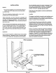
PA.T.O. I ,,,,_,,.0_, I 0','_ I _'"_ I SU"ERSEOES I ""_"00_"I PA_E,'O_,O FIGURE1 INSTRUCTIONFORSUPPORTING PWCUNITS Wall Sleeve 7 x 22 Min. OpeningTo A#ignwith'Return Air Openingin Unit. Vibration IsolatingMaterial % Plywood FIGURE2 5/8 " I.D. PLASTIC (FURNISHED) DRAIN PAN CHASSIS DRAIN 'ASSEMBLY (FURNISHED) 5/8" I,O. PLASTIC TU"BE(FURNISHEO] \ 5/8" O.O. DRAIN _LINEAND TRAP (iNSTALLERSUPPLIED) RETURN AIR DUCT\
.ARTNO. I "f9"BogI OATE I 2"t'g6I .SUPERSEOES I 4119'0094 [ PAGESOFtO LIMITATIONS The unit shouldbe installedin accordancewith all nationaland local safetycodes. Limitationsof the unit and appropriateaccessoriesmust also be observed. The unit must NOTbe installedwith any ductwork in the outdoorairstream,The outdoor fan is not designedto operate againstany additionalstatic pressure.
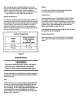
It an installation is made in which it is more1 desirable to mount the filter exterior to unit, in the return work, or tO I PA.TNo I .tt9..o96 I DATE 2196 I SUPERSEDES I the,rig.DO9. I ductPAGE,O. olherwise, either the permanent filter supplied or a disposable filter may be used. If a disposable filter is used, the minimum area required is as follows: MOOEL NO. PWC 182 PWC 242 PWC 302 FILTER AREA(MtN.) 480 sq. in. 480 sq. in. 480 sq. in.
PA...o, I .,,9.o09.I ANIDNSTALLATION MAINTENANCE INSTRUCTIONS PWCSERIES SELF-CONTAINED HEATPUMP PART NO.] 4,,94°O94 I OA_E ] 4-,5-94 I SU_RSEOES I .EW I Manulaclured By ARMSTRONG AIR CONDITIONING INC, A LENNOXInternationalInc.
! PART NO. I 4,tg4ooB4 I DATE I 4lsg, I SUPERSEOES I NEWI PAGE2OFlO GENERAL Theseinstructionsexplainthe recommendedmethodof installationof the PWCheal pumpunit and associatedelectrical wiring. This unil is designed and approvedfor use as a self-contained air Io air heat pump system.
I PA,,NO. I ,, g,o094 I DATE I '-fS-g'I SUPERSEDES I ,EW I LOCATION PAGE3OF,O The design is certifiedfor through-the-wallinstallationonly. The interiorportionsof theunit may be surroundedby a cJoset with clearancesto combustiblematerial held to O" at sides, 0" top and 0" frontof the plenum.
NEW [ PAGE4 OF 10 I PART.O. I "(940094 [ DArE I 4-_5-9' I SUPERSEDES FIGURE1 INSTRUCTIONFORSUPPORTING PWCUNITS WallSleeve 7 x 22 Mio. OpeningTo Align with Return Air Opening _n Unit. ] L_ VibrationisolatingMaterial % FIGURE2 5/8 "I.D. PLASTIC (FURNISHED) CHASSISDRAIN (FURNISHED) 5/8" I.D. PLASTIC TUBE (FURNISHED) \ RETURN NR DUCT \ \ \ 518" O.O.
PA,TNO I 4tt94OOB4 I DA E I 41594]SUPERSEDES I NEWI PAGE OFtO LIMITATIONS The unit shouldbe installedin accordance with all national and localsafety codes. Limitationsof the unit and appropriateaccessoriesmust also be observed. Theunit mustNOTbe installedwith any ductworkin the outdoor airstream.Theoutdoorfan is notdesignedto operate againstany additionalstatic pressure. Minimum and maximum,operating conditionsmust be observed to assure maximumsystem performancewith minimum servicerequired.
PART NO. ] 41194D094 ] DATE ] 4-15-94 ] SUPERSEDES ] NEW ] PAGE6 OF 10 If an installation is madein which it is more desirable tomount the filter exterior tothe unit, in the return duct work, or otherwise, either the permanent filter suppliedor a disposable filter may be used. If a disposable filter is used, the minimum area required is as follows: MODELNO, PWC 182 PWC 242 PWC 302 FILTERAREA(MIN.) 480 sq. in, 480 sq. in. 480 sq. in.
PA,T,O. I ,tt,,O0,, ( [ l SUPERSEOES I NEW l PAGE OFtO The defrost controlwill initiate a defrosl cycle if the time period has elapsedand the defrost sensor detects a temperature below freezfng. At the slart of the defrost cycle, Ihe defrost ControlwUIenergize the reversing valve solenoid,shift(ng the reversing valve and de-energizing the outdoor fan. The defrost reraywilt alsoclose, energizing auxiliary heat for increased comfortduring defrost.
[ PARTNO I 4t_g4DOg4 I DATE ] 4iS-g,I SUPERSEOES I NEWI RAGE8OF_O MAINTENANCE NORMAL MAINTENANCE WARNING: PRIOR TO ANY OF THE FOLLOWING MAINTENANCE PROCEDURESSHUT OFF ALL ELECTRICALPOWERTO THE UNIT. FAILTURETO DOSO COULDCAUSE PERSONALINJURY. Periodic inspectionand maintenancenormallyconsistsof changing or cleaningfilters and (under someconditions) cleaning the coils. FILTER- supplied. Inspect oncea month.Replacedisposable,or clean permanenttypeas necessary. DONOTreplace permanenttype with disposable.
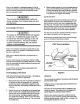
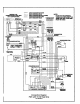
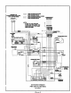
I _,,9_Do9. I OA_E l .-_5-g_ l SU_E.SEOES l .EW I ,_GEgOF,O llllll llllll ?AND 10 PVC 0NLY RED lira CAP. UOI'CR VZOI.[T >( HIGH _EE EV.OV_ Rm RE9 8L_X CmTm U m.L0W C/P/Z:IT_-RIJ_ eTI O / V/I.VE © B.
I 1PA'_RT N0. I 411941)094 I DATE 3Ct/'ZsO-t-60 SUPPLTWI?H ¥[N. 75'€ €_ WIIaE CX_Z:_zT t i _ cz_qcuzT 2 ) -- I 4-15-94 I _ LINK; tOLTAE_'II_O -- Lof vo.T_4[_ SUPERSEDES I PAGE 10 OF 10 NEW 11.10_6?AT NO"_j F AWlG_ THE CtqXOINAL IrlRl_ _ _ T14£ SAUESIZE A_P TYPEWIRE i_T 0£ USf_, BUJE IIIIII IIIIII VXa.k'T HZOH mAC= I €_rxcTOR aU_a_ Yn.LOW I 'flg.LOw CAPAC l TIOR-RUN V_ =lJu_ Ot.UE I ,.
PWC SELF CONTAINED THRU-THE-WALL HEAT PUMP Part No.
Part N_ 30790F089 $upereedes 30790G082 Date. 6-1-89 Page2__2__of 12 FORWARD This is a self-contained heat pump designed for Installation through an exterior wall. The unit is Underwriters' Laboratories listed under heat pumps and is in compliance with Underwriters Standard, UL 559. The unit is also certified to the Air Conditioning and Refrigeration Institute as complying to ARI Standard 240.
PartNo. 307SOF089 Supersedes 30790G082 Date 6-1-89 Page _of 12 INTRODUCTION This manual is intended to familiarize the installer, serviceman, and the user with the installation, operation and maintenance of this thru-the-wall heat pump. This unit is shipped from the factory in one package completely assemblied and wired. A specially designed trap assembly is shipped, secured to the air return area in lower front of unit.
Part No. 30?90F089 Date Supersedes 30790G082 ,, Page _of TABLE OF CONTENTS " Page INSTALLATION Site Preparation ............................ Condensate and Defrost Drain ................. Electrical Connections ........................ Thermostat ............................... Air Filter ......... ; ...................... Duct Work ............................... Unit Checkout Procedure ..................... 5 6 7-8 9 9 9 10 OPERATION INSTRUCTIONS Heating Operation ..........................
Part No. 307g0F089 Supersedes 30790G082 Date. Page_of 6-1-89 12 INSTALLATION Site Preparation Tills unit is approved for thru-the.wall installation, with zero clearance to combustible material. The unit must be installed within a conditioned space to prevent freezing of defrost water in trap assembly and to avoid jacket heat loss and surface condensation problem. This unit must be installed with the wall sleeve specified for this unit.
Part No. 30790F089 Date Supersedes 30790G082 Page_of 6-1-89 12 INSTALLATION Before sliding unit into sleeve, remove 5 screws and washers from top panel. Slide unit into sleeve until the angle on top of the unit lines up with the top flange of the sleeve, and should almost touch. Fasten unit to sleeve with the 5 screws and washers above. Condensate and Defrost Drain The condensate drain trap furnished pieces of plastic tubing.
Pan No. 307g0F089 Supemedes 30790G082 Date Page T 6-1_9 of 12 INSTALLATION Electrical Connections All wiring to unit must comply with the national Electrical Code NFPA No. 70 or local codes, where they prevail. ANY ALTERNATION OF INTERNAL WIRING CAN VOID UNDERWRITER'S APPROVAL, ARI CERTIFICATION AND MANUFACTURE'S LIMITED WARRANTY. The series and rating plates indicate the operating voltages, phase, ampacities and maximum fuse size and electric heater ratings.
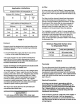
Part No. 30790F089 Supersedes 30790G082 Date Page_ 208-230 voit 1 Ph. power supply I I I [] FIGURE 3. SINGLE ENTRY SUPPLY Remove internal for multiple entry Supply. PWC18E4.8, PWGI8E7.2 PWC24E4.8, PWC24E7.2 208-230V 208.230V 1 Ph. power supply 1 Ph power supply t-_ ICircuit I No.I Circuit I"_ No. 2I I I I I FIGURE 4, MULTIPLE ENTRY SUPPLY PWC18E9.2, PWC18E10.7 PWC24Eg.2, PVVC24ElO.7 r I Circuit ! No.1 I FIGURE 5. MULTIPLE ENTRY SUPPLY PWC18E14.7 PWC24E14.7 Circuit No.
Part No. 30790F089 Date Supersedes 30790G082 Page_of 6-1-89 12 Thermostat This unit requires special thermostat for operation. See product specification sheets or label on unit for manufacture's part number. Install the thermostat according to directions furnished with It. Select a location in a room having the most wall or window area exposed to the outsid_ Locate on an inside wall, away from drafts, sunlight or any heat producing appliances.
Part No. 30790F089 Supersedes 30790G082 Date Page 10 6-1-89 of INSTALLATION A. Unit 1. 2. 3. Check-Out Procedure - IMPORTANT Filter(s) must be clean and in place as to filter all air passing over indoor coil, Set thermostat to "OFF" position. Check that correct size fuses are installed for unit. 4. All panels must be in place. 5. Turn on main power to unit. B. Heating Check 1. Set fan switch to "AUTO". 2. Set thermostat lever to lowest temperatuf'e. 3.
Part No. 30790F089 Supersedes 30790G082 Date. Page 11 6-1-89 of 12 OPERATION INSTRUCTIONS The following instructions are to be followed to obtain years of trouble free operation of your year-around comfort system. To start unit turn on main power (may have two disconnect switches).
Part No. 30790F089 Supersedes 30790G082 Date, Page 11 6-1o89 of 12 OPERATION INSTRUCTIONS The following instructions are to be followed to obtain years of trouble free operation of your year-around comfort system. To start unit turn on main power (may have two disconnect switches).