
Air Conditioner User Manual


Page 11
CBX25UH SERIES
2
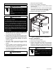
BLUE (MED)
RED (L0)
BLACK (HI)
YELLOW (COM)
5
BLOWER RELAY
BLOWER RELAY
PLASTIC CAPS
4-PIN
BLOWER CONNECTOR
HARNESS
CHANGING BLOWER SPEED
Figure 13. Changing Blower Speed
NOTE — Refer to wiring diagram located on the unit access panel (or figure 13 above) and blower performance (table 2).
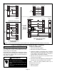
S All air data measured external to unit with 1 inch non-pleated air filter in place.
S All factory settings are medium speed except the -48 which is set to low speed from the factory.
S All data given while air handler is operating with a dry DX coil.
Table 2. CBX25UH Blower Performance (3-Speed PSC) - 240V (CFM @ ESP. - in. W. C.)
Air Handler
Model
Blower Speed .10” WC .20” WC .30” WC .40” WC .50” WC
18
Low (Red)
Med (Blue)
High (Black)
510
670
905
495
650
865
475
630
820
420
595
770
325
505
705
24
Low (Red)
Med (Blue)
High (Black)
630
885
1130
625
875
1100
615
850
1070
610
820
1010
580
780
950
30
Low (Red)
Med (Blue)
High (Black)
900
1075
1240
865
1060
1210
830
1030
1170
780
985
1135
740
940
1085
36
Low (Red)
Med (Blue)
High (Black)
1160
1500
1660
1140
1445
1575
1115
1385
1495
1085
1300
1405
990
1200
1390
42
Low (Red)
Med (Blue)
High (Black)
1325
1490
1820
1315
1465
1770
1300
1440
1690
1275
1395
1600
1225
1315
1500
48
Low (Red)
Med (Blue)
High (Black)
1775
1995
2070
1710
1895
1970
1645
1800
1850
1565
1685
1719
1470
1560
1595
60
Low (Red)
Med (Blue)
High (Black)
1675
1965
2140
1630
1925
2085
1580
1875
2000
1520
1800
1895
1450
1695
1795
S Blower Performance (CFM vs. ESP inches H2O)
S Cooling speeds should not be reduced below factory setting.
S Units with electric heat approved at 0.5” maximum and medium blower speed minimum.