
Air Conditioner User Manual


Page 12
Check-out Procedures
NOTE - Refer to outdoor unit installation instructions for
system start-up instructions and refrigerant charging
instructions.
PRE‐START‐UP CHECKS
S Is the air handler properly and securely installed?
S If horizontally configured, is the unit sloped up to 5/8
inch toward drain lines?
S Will the unit be accessible for servicing?
S Has an auxiliary pan been provided under the unit with
separate drain for units installed above a finished
ceiling or in any installation where condensate
overflow could cause damage?
S Have ALL unused drain pan ports been properly
plugged?
S Has the condensate line been properly sized, run,
trapped, pitched, and tested?
S Is the duct system correctly sized, run, sealed, and
insulated?
S Have all cabinet openings and wiring been sealed?
S Is the indoor coil factory‐installed TXV properly sized
for the outdoor unit being used?
S Have all unused parts and packaging been disposed
of?
S Is the filter clean, in place, and of adequate size?
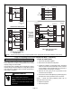
S Is the wiring neat, correct, and in accordance with the
wiring diagram?
S Is the unit properly grounded and protected (fused)?
S Is the thermostat correctly wired and in a good
location?
S Are all access panels in place and secure?
CHECK BLOWER OPERATION
S Set thermostat to FAN ON.
S The indoor blower should come on.
CHECK COOLING OPERATION
S Set thermostat to force a call for cooling
(approximately 5ºF lower than the indoor ambient
temperature).
S The outdoor and indoor units should come on
immediately.
S Check the airflow from a register to confirm that the
system is moving cooled air.
S Set the thermostat 5ºF higher than the indoor
temperature. The indoor blower and outdoor unit
should cycle off. Air handler should cycle off 45
seconds after the outdoor unit shuts off.
CHECK ELECTRIC HEATER (IF USED)
S Set thermostat to call for auxiliary heat (approximately
5°F above ambient temperature). The indoor blower
and auxiliary heat should come on together. Allow a
minimum of 3 minutes for all sequencers to cycle on.
S Set the thermostat so that it does not call for heat.
Allow up to 5 minutes for all sequencers to cycle off.
Operation
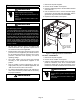
TIME DELAY RELAY
Blower time delay operation:
1. When cooling demand is initiated, there is a 1 second
motor-on delay.
2. After the motor-on delay expires, motor ramps up to
100% and runs at 100% until cooling demand is
satisfied.
3. Once demand is met, motor runs at 100% for 45
seconds.
4. Motor ramps down to stop.
1
SECOND
DELAY
OFF
100%
CFM
100%
CFM
45
SECS
COOLING
DEMAND
1
2
34
Figure 14. Blower Time Delay
COOLING (COOLING ONLY OR HEAT PUMP)
When the thermostat calls for cooling, 24 volts is put on the
blower time-delay relay coil and then the indoor blower
relay energizes. The normally open contacts close,
causing the indoor blower motor to operate. The circuit
between R and Y is completed, closing the circuit to the
contactor in the outdoor unit, starting the compressor and
outdoor fan motor.
On heat pumps, circuit R and O energizes the reversing
valve, switching the valve to the cooling position. (The
reversing valve remains energized as long as the
thermostat selector switch is in the COOL position.)
At the completion of the cooling demand the indoor blower
and outdoor unit should cycle off. Air handler should cycle
off 45 seconds after the outdoor unit shuts off.
HEATING (ELECTRIC HEAT ONLY)
When the thermostat calls for heat, the circuit between R
and W is completed, and the heat sequencer is energized.
A time delay follows before the heating elements and the
indoor blower motor come on. Units with a second heat
sequencer can be connected with the first sequencer to W
on the thermostat subbase, or they may also be connected
to a second stage on the subbase.
HEATING (HEAT PUMP)
When the thermostat calls for heating, 24 volts is put on the
blower time-delay relay coil. Then normally open contacts
close, causing the indoor blower motor to operate. The
circuit between R and Y is completed, closing the circuit to
the contactor in the outdoor unit, starting the compressor
and outdoor fan motor.
If the room temperature should continue to fall, the circuit
between R and W1 is completed by the second‐stage heat
room thermostat. Circuit R-W1 energizes a heat
sequencer. The completed circuit will energize
supplemental electric heat (if applicable). Units with a