
Air Conditioner User Manual

Page 8
IMPORTANT
If a highefficiency filter is being installed as part of this
system to ensure better indoor air quality, the filter must
be properly sized. Highefficiency filters have a higher
static pressure drop than standardefficiency glass/foam
filters. If the pressure drop is too great, system capacity
and performance may be reduced. The pressure drop
may also cause the limit to trip more frequently during the
winter and the indoor coil to freeze in the summer, result
ing in an increase in the number of service calls.
Before using any filter with this system, check the spe
cifications provided by the filter manufacturer against the
data given in the appropriate Lennox Product Specifica
tions bulletin. Additional information is provided in Ser
vice and Application Note ACC002 (August 2000).
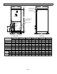
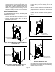
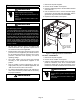
Supply plenum should be the same size as the flanged
opening provided around the blower outlet and should
extend at least 3 ft. from the air handler before turning or
branching off plenum into duct runs. The plenum forms an
extension of the blower housing and minimizes air
expansion losses from the blower.
INSTALLING DUCT SYSTEM
Connect supply air duct to the flange on top of the air
handler. If an isolation connector is used, it must be
nonflammable.
A return air duct system is recommended. If the unit is
installed in a confined space or closet, a return connection
must be run, full size, to a location outside the closet.
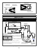
Connecting Refrigerant Lines
Refrigerant lines must be connected by a qualified
technician in accordance with established procedures.
IMPORTANT
Refrigerant lines must be clean, dehydrated, refrig
erant-grade copper lines. Air handler coils should be
installed only with specified line sizes for approved sys
tem combinations.
Handle the refrigerant lines gently during the installation
process. Sharp bends or possible kinking in the lines will
cause a restriction.
Do not remove the caps from the lines or system connec
tion points until connections are ready to be completed.
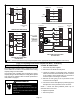
1. Route the suction and liquid lines from the fittings on
the indoor coil to the fittings on the outdoor unit. Run
the lines in as direct a path as possible avoiding
unnecessary turns and bends.
2. Make sure that the suction line is insulated over the
entire exposed length and that neither suction nor
liquid lines are in direct contact with floors, walls, duct
system, floor joists, or other piping.
3. Connect the suction and liquid lines to the evaporator
coil.
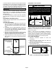
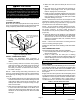
4. To avoid damaging the rubber grommets in the cabinet
while brazing, slide the rubber grommets over the
refrigerant lines until they are away from the heat
source.
5. Braze using an alloy of silver or copper and
phosphorus with a melting point above 1,100°F
(593°C).
NOTE — Do not use soft solder.
6. Reinstall the rubber grommets after brazing is
finished.
7. Make sure outdoor unit has been put in place
according to the Installation Instructions and is
connected to the refrigerant lines.
Sealing the Unit
Seal the unit so that warm air is not allowed into the
cabinet. Warm air introduces moisture, which results in
water blow-off problems. This is especially important when
the unit is installed in an unconditioned area.
If installed in an unconditioned space, sealant should be
applied around the electrical wires, refrigerant tubing, and
condensate lines where they enter the cabinet.
WARNING
There must be an airtight seal between the bottom of the
air handler and the return air plenum. Use fiberglass
sealing strips, caulking, or equivalent sealing method
between the plenum and the air handler cabinet to
ensure a tight seal. Return air must not be drawn from a
room where this air handler or any gas-fueled appliance
(i.e., water heater), or carbon monoxide-producing
device (i.e., wood fireplace) is installed.
IMPORTANT
When sealing the cabinet, be sure to seal closed any
space around the holes where the drain lines exit the
cabinet using duct tape and/or Permagum. Warm air
must not be allowed to enter through any gaps or holes
in the cabinet.
Make sure the liquid line and suction line entry points are
sealed with either ARMAFLEX material or with
Permagum. Permagum may also be used to seal around
the main and auxiliary drains and around open areas of
electrical inlets.