INSTALLATION INSTRUCTIONS ML193UH E 2013 Lennox Industries Inc. Dallas, Texas, USA MERIT® SERIES GAS FURNACE UPFLOW / HORIZONTAL AIR DISCHARGE 507121-01 08/2013 Supersedes 06/2013 Litho U.S.A. THIS MANUAL MUST BE LEFT WITH THE HOMEOWNER FOR FUTURE REFERENCE This is a safety alert symbol and should never be ignored. When you see this symbol on labels or in manuals, be alert to the potential for personal injury or death.
ML193UH Unit Dimensions - inches (mm) 1NOTE − 60C and 60D size units that require air volumes 1800 cfm or over (850 L/s) must have one of the following 1. Single side return air with transition, to accommodate 20 x 25 x 1 in. (508 x 635 x 25 mm) cleanable air filter. Required to maintain proper air velocity. 2. Single side return air with optional Return Air Base 3. Bottom return air. 4. Return air from both sides. 5. Bottom and one side return air. See Blower Performance tables for additional information.
ML193UH Gas Furnace Shipping and Packing List The ML193UH Category IV gas furnace is shipped ready for installation in the upflow or horizontal position. The fur nace is shipped with the bottom panel in place. The bottom panel must be removed if the unit is to be installed in hori zontal or upflow applications with bottom return air. The ML193UH can be installed as either a Direct Vent or a Non-Direct Vent gas central furnace. The furnace is equipped for installation in natural gas ap plications.
Gas Code is available from the following address: American National Standards Institute, Inc. 11 West 42nd Street New York, NY 10036 In Canada, installation must conform with current National Standard of Canada CSA‐B149 Natural Gas and Propane Installation Codes, local plumbing or waste water codes and other applicable local codes.
D Air filters must be replaced upon construction comple tion. D The input rate and temperature rise must be set per the furnace rating plate. D One hundred percent (100%) outdoor air must be pro vided for combustion air requirements during construc tion. Temporary ducting may supply outdoor air to the furnace. Do not connect duct directly to the furnace.
will build to the point that a downdraft can occur in the fur nace vent pipe or chimney. As a result, combustion gases enter the living space creating a potentially dangerous situ ation. infiltration. If the furnace is located in a building of tight construction with weather stripping and caulking around the windows and doors, follow the procedures in the Air from Outside section.
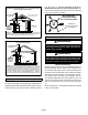
Air from Outside If air from outside is brought in for combustion and ventila tion, the confined space shall be provided with two perma nent openings. One opening shall be within 12” (305mm) of the top of the enclosure and one within 12” (305mm) of the bottom. These openings must communicate directly or by ducts with the outdoors or spaces (crawl or attic) that freely communicate with the outdoors or indirectly through verti cal ducts.
EQUIPMENT IN CONFINED SPACE - ALL AIR FROM OUTSIDE (All Air Through Ventilated Attic) ROOF TERMINATED EXHAUST PIPE leg). See figure 10. The bolt and washer must be re moved before the furnace is placed into operation. Af ter the bolt and washer have been removed, the rigid leg will not touch the blower housing.
SETTING EQUIPMENT UPFLOW APPLICA TION UNIT FRONT UNIT FRONT AIR FLOW AIR FLOW FRONT VIEW SIDE VIEW 1/2” max. SIDE VIEW HORIZONTAL APPLICATION UNIT FRONT AIR FLOW 1/2” max. END VIEW FRONT VIEW Unit must be level side-to-side. Unit may be positioned from level to 1/2” toward the front to aid in draining.
Return Air Guidelines WARNING Improper installation of the furnace can result in per sonal injury or death. Combustion and flue products must never be allowed to enter the return air system or air in the living space. Use sheet metal screws and joint tape to seal return air system to furnace. In platform installations with furnace return, the fur nace should be sealed airtight to the return air ple num. A door must never be used as a portion of the return air duct system.
Optional Return Air Base (Upflow Applications Only) CONDENSATE TRAP FURNACE FRONT INDOOR AIR QUALITY CABINET (PCO, Filter Cabinet, etc.
The ML193UH furnace can be installed in horizontal ap plications with either right- or left-hand air discharge. Refer to figure 17 for clearances in horizontal applications.
Duct System INTAKE PIPE *GAS CONNECTION EXHAUST PIPE RAISED PLATFORM SERVICE PLATFORM FIGURE 19 Return Air -- Horizontal Applications Return air may be brought in only through the end of a fur nace installed in the horizontal position. The furnace is equipped with a removable bottom panel to facilitate instal lation. See figure 15. Filters This unit is not equipped with a filter or rack. A field-pro vided high velocity rated filter is required for the unit to oper ate properly.
CAUTION IMPORTANT Solvent cements for plastic pipe are flammable liq uids and should be kept away from all sources of ignition. Do not use excessive amounts of solvent cement when making joints. Good ventilation should be maintained to reduce fire hazard and to minimize breathing of solvent vapors. Avoid contact of ce ment with skin and eyes.
TABLE 3 OUTDOOR TERMINATION USAGE* STANDARD Input Size 045 070 090 110 135 Vent Pipe Dia. in.
NOTE - Assembly should be completed within 20 sec onds after last application of cement. Hammer blows should not be used when inserting pipe. 8 - After assembly, wipe excess cement from pipe at end of fitting socket. A properly made joint will show a bead around its entire perimeter. Any gaps may indicate an improper assembly due to insufficient solvent. 9 - Handle joints carefully until completely set.
Use the following steps to correctly size vent pipe diameter. Vent Piping Guidelines The ML193UH can be installed as either a Non-Direct Vent or a Direct Vent gas central furnace. NOTE - In Non‐Direct Vent installations, combustion air is taken from indoors and flue gases are discharged out doors. In Direct Vent installations, combustion air is taken from outdoors and flue gases are discharged outdoors. Intake and exhaust pipe sizing -- Size pipe according to tables 4 and 5.
TABLE 5 Maximum Allowable Intake or Exhaust Vent Length in Feet NOTE - Size intake and exhaust pipe length separately. Values in table are for Intake OR Exhaust, not combined total. Both Intake and Exhaust must be same pipe size. NOTE - Additional vent pipe and elbows used to terminate the vent pipe outside the structure must be included in the total vent length calculation.
TYPICAL EXHAUST PIPE CONNECTIONS IN UPFLOW DIRECT OR NON-DIRECT VENT APPLICATIONS Pipe size determined in table 5 2” 2” 2” 3” 2” or 2” or TRANSITION EXHAUST *2” DO NOT transition from smaller to larger pipe in horizontal runs of exhaust pipe. * When transitioning up in pipe size, use the shortest length of 2” PVC pipe possible. NOTE − Exhaust pipe and intake pipe must be the same diameter.
TYPICAL AIR INTAKE PIPE CONNECTIONS IN UPFLOW DIRECT VENT APPLICATIONS Pipe size determined in table 5 2” or 3” TRANSITION AIR INTAKE *2” 2” 2” 2” or 2” * When transitioning up in pipe size, use the shortest length of 2” PVC pipe possible. NOTE − Intake and exhaust pipe must be the same diameter.
Intake Piping The ML193UH furnace may be installed in either direct vent or non-direct vent applications. In non-direct vent applications, when intake air will be drawn into the furnace from the surrounding space, the indoor air quality must be considered and guidelines listed in Combustion, Dilution and Ventilation Air section must be followed.
CAUTION If this unit is being installed in an application with combustion air coming in from a space serviced by an exhaust fan, power exhaust fan, or other device which may create a negative pressure in the space, take care when sizing the inlet air opening. The in let air opening must be sized to accommodate the maximum volume of exhausted air as well as the maximum volume of combustion air required for all gas appliances serviced by this space.
TABLE 7 Maximum Allowable Exhaust Vent Pipe Length (in ft.) Without Insulation In Unconditioned Space For Winter Design Temperatures Single - Stage High Efficiency Furnace Winter Design Temperatures1 °F (°C) Vent Pipe Diameter Unit Input Size 045 070 090 110 135 PVC PVC PVC PVC PVC 32 to 21 2 in. 26 44 44 24 N/A (0 to -6) 2-1/2 in. 18 32 50 58 N/A 3 in. 14 26 38 55 60 2 in 16 28 40 24 N/A 2-1/2 in. 12 20 30 44 N/A 3 in. 9 16 26 32 40 2 in.
VENT TERMINATION CLEARANCES FOR NON-DIRECT VENT INSTALLATIONS IN THE USA AND CANADA INSIDE CORNER DETAIL G H A D E B L Fixed Closed Operable F B B C I Fixed Closed Operable M B K J A B AREA WHERE TERMINAL IS NOT PERMITTED AIR SUPPLY INLET VENT TERMINAL US Installations1 A= Clearance above grade, veranda, porch, deck or balcony B= Clearance to window or door that may be opened C= Clearance to permanently closed window D= Vertical clearance to ventilated soffit located above the te
VENT TERMINATION CLEARANCES FOR DIRECT VENT INSTALLATIONS IN THE USA AND CANADA INSIDE CORNER DETAIL G H A D E B L Fixed Closed Operable F B B C I Fixed Closed Operable M B A K J B AREA WHERE TERMINAL IS NOT PERMITTED AIR SUPPLY INLET VENT TERMINAL US Installations1 A= Clearance above grade, veranda, porch, deck or balcony B= Clearance to window or door that may be opened C= Clearance to permanently closed window D= Vertical clearance to ventilated soffit located above the termina
Details of Intake and Exhaust Piping Terminations for Direct Vent Installations NOTE - In Direct Vent installations, combustion air is taken from outdoors and flue gases are discharged to outdoors. NOTE - Flue gas may be slightly acidic and may adversely affect some building materials. If any vent termination is used and the flue gasses may impinge on the building ma terial, a corrosion-resistant shield (minimum 24 inches square) should be used to protect the wall surface.
7 - If intake and exhaust piping must be run up a side wall to position above snow accumulation or other ob structions, piping must be supported. At least one bracket must be used within 6” from the top of the el bow and then every 24” (610mm) as shown in figure 42, to prevent any movement in any direction. When exhaust and intake piping must be run up an outside wall, the exhaust piping must be terminated with pipe sized per table 8.The intake piping may be equipped with a 90° elbow turndown.
FIELD FABRICATED WALL TERMINATION NOTE − FIELD−PROVIDED REDUCER MAY BE REQUIRED TO ADAPT LARGER VENT PIPE SIZE TO TERMINATION 2” (51mm) 3” (76mm) Vent Pipe Vent Pipe D D B Intake Elbow C1 A B C2 A STRAIGHT APPPLICATION A− Minimum clearance above grade or average snow accumulation 12” (305 mm) 12” (305 mm) B− Maximum horizontal separation between intake and exhaust 6” (152 mm) 6” (152 mm) C1 -Minimum from end of exhaust to inlet of intake 8” (203 mm) 8” (203 mm) C2 -Minimum from end of exh
ML193UH DIRECT VENT APPLICATION USING EXISTING CHIMNEY 3”-8” (76mm-203mm) STRAIGHT-CUT OR ANGLE-CUT IN DIRECTION OF ROOF SLOPE * 8” - 12” (203mm - 305mm) Minimum 12” (305MM) above chimney top plate or average snow accumulation INTAKE PIPE INSULATION (optional) 3” (76mm) OR 2” (51mm) PVC SHOULDER OF FITTINGS PROVIDE SUPPORT OF PIPE ON TOP PLATE SHEET METAL TOP PLATE INSULATE TO FORM SEAL SIZE TERMINATION PIPE PER TABLE 8. 12” (305mm) ABOVE AVE.
tions the field provided vent must be a minimum 1” to a maximum 2” length above the condensate drain outlet connection. Any length above 2” may result in a flooded heat exchanger if the combined primary drain line were to become restricted. Horizontal furnace (figure 53) - In horizontal furnace applications the field provided vent must be a mini mum 4” to a maximum 5” length above the condensate drain outlet connection.
CONDENSATE TRAP LOCA Condensate Trap With Optional Overflow Switch (UnitTIONS shown in upflow position with remote trap) From Evaporator Coil Horizontal Furnace4” Min. to 5” Max. above condensate drain connection) Field ProvidedVent Min. 1” Above Condensate Drain Connection 1” Min. 2” Max. Furnace Condensate Drain Connection *5’ max. PVC PipeOnly Optional To Drain *Piping from furnace must slope down a minimum of 1/4” per ft. toward trap.
ML193UH with Evaporator Coil Using a Separate Drain (Unit shown in horizontal left-hand discharge position) Field Provided Vent (4” min. to 5” max. above condensate connection) Evaporator Coil 4”min 5”max 5’ max. PVC Pipe Only Condensate Drain Connection (Trap at coil is optional) Drain Pan *Piping from furnace and evaporator coil must slope down a minimum 1/4” per ft. toward trap FIGURE 51 .
TRAP / DRAIN ASSEMBLY USING 1/2” PVC OR 3/4” PVC Optional Condensate Drain Connection Adapter 3/4 inch slip X 3/4 inch mpt (not furnished) 90° Street Elbow 3/4 inch PVC (not furnished) Adapter 3/4 inch slip X 3/4 inch mpt (not furnished) Condensate Drain Connection In Unit 90° Street Elbow 3/4 inch PVC ( furnished) 1 (25 mm) Min. 2 (50 mm) Max.
4 - Piping should be sloped 1/4 inch per 15 feet (6mm per 5.6m) upward toward the gas meter from the furnace. The piping must be supported at proper intervals, ev ery 8 to 10 feet (2.44 to 3.05m), using suitable hangers or straps. Install a drip leg in vertical pipe runs to serve as a trap for sediment or condensate. 5 - A 1/8” N.P.T. plugged tap or pressure post is located on the gas valve to facilitate test gauge connection. See figure 61.
Left Side Piping (Standard) Right Side Piping (Alternate) AUTOMATIC GAS VALVE (with manual shut-off valve) MANUAL MAIN SHUT-OFF VALVE Bellows Grommet Plug MANUAL MAIN SHUT-OFF VALVE Plug GROUND JOINT UNION GROUND JOINT UNION Gas Valve Gas Valve DRIP LEG Bellows Grommet DRIP LEG FIELD PROVIDED AND INSTALLED NOTE - BLACK IRON PIPE ONLY TO BE ROUTED INSIDE OF CABINET FIGURE 57 Horizontal Applications Possible Gas Piping Configurations MANUAL MAIN SHUT-OFF VALVE MANUAL MAIN SHUT-OFF VALVE Horiz
TABLE 9 GAS PIPE CAPACITY - FT3/HR (kL/HR) Length of Pipe-Feet(m) 50 60 70 (15.240) (18.288) (21.336) Nominal Iron Pipe Size -Inches(mm) Internal Diameter -Inches(mm) 10 (3.048) 20 (6.096) 30 (9.144) 40 (12.192) 1/2 (12.7) .622 (17.799) 175 (4.96) 120 (3.40) 97 (2.75) 82 (2.32) 73 (2.07) 66 (1.87) 3/4 (19.05) .824 (20.930) 360 (10.19) 250 (7.08) 200 (5.66) 170 (4.81) 151 (4.28) 1 (25.4) 1.049 (26.645) 680 (19.25) 465 (13.17) 375 (10.62) 320 (9.06) 1-1/4 (31.75) 1.380 (35.
Complete the wiring connections to the equipment. Use the provided unit wiring diagram and the field wiring shown in figure 60. Use 18-gauge wire or larger that is suitable for Class II rating for thermostat connections. Electrical ELECTROSTATIC DISCHARGE (ESD) Precautions and Procedures CAUTION Electrostatic discharge can affect elec tronic components. Take precautions to neutralize electrostatic charge by touching your hand and tools to metal prior to handling the control.
Generator Use - Voltage Requirements The following requirements must be kept in mind when specifying a generator for use with this equipment: D The furnace requires 120 volts + 10% (Range: 108 volts to 132 volts) D The furnace operates at 60 Hz + 5% (Range: 57 Hz to 63 Hz) D The furnace integrated control requires both polarity and proper ground.
Integrated Control INTEGRATED CONTROL (Automatic Hot Surface Ignition System) HUM LINE XFMR EAC COOL HEAT PARK CONT NEUTRALS TWIN TERMINAL DESIGNATIONS Humidifier (120VAC) Input (120VAC) Transformer (120VAC) Indoor Air Qality Accessory Air Cleaner (120VAC) Blower - Cooling Speed (120VAC) Blower - Heating Speed (120VAC) Dead terminals to park alternate spd taps Continuous blower Neutral terminals (120VAC) Twinning Terminal (24VAC) LED PUSH BUTTON TWIN BLOWER OFF DELAY JUMPER FIGURE 1 Note - This contro
5 - Wait for the combustion air inducer to stop. Set the thermostat to initiate a heating demand and again al low the burners to fire for approximately 3 minutes. 6 - Adjust the thermostat to deactivate the heating de mand and wait for the combustion air inducer to stop. At this point, the trap should be primed with sufficient water to ensure proper condensate drain operation. Unit Start-Up FOR YOUR SAFETY READ BEFORE OPERATING WARNING Do not use this furnace if any part has been under water.
4 - Move gas valve switch to OFF. 5 - Replace the upper access panel. Failure To Operate If the unit fails to operate, check the following: 1 - Is the thermostat calling for heat? 2 - Are access panels securely in place? 3 - Is the main disconnect switch closed? 4 - Is there a blown fuse or tripped breaker? 5 - Is the filter dirty or plugged? Dirty or plugged filters will cause the limit control to shut the unit off.
Proper Combustion High Altitude Information Furnace should operate minimum 15 minutes with correct manifold pressure and gas flow rate before checking com bustion. Take combustion sample beyond the flue outlet and compare to the tables below. TABLE 12 ML193 CO2% For Nat CO2% For L.P. Unit -045 -070 -090 7.2 - 7.9 8.6 - 9.3 -110 -135 The maximum carbon monoxide reading should not exceed 50 ppm.
Testing for Proper Venting and Sufficient Combustion Air for Non-Direct Vent Applications WARNING CARBON MONOXIDE POISONING HAZARD! 3- Failure to follow the steps outlined below for each appliance connected to the venting system being placed into operation could result in carbon monox ide poisoning or death.
Other Unit Adjustments HEAT FAN‐OFF TIME IN SECONDS Primary Limit. The primary limit is located on the heating compartment vestibule panel. This limit is factory set and requires no ad justment. NO JUMPER Flame Rollout Switches (Two) Fan Control The fan on time of 30 seconds is not adjustable. The fan off delay (amount of time that the blower operates after the heat demand has been satisfied) may be adjusted by changing the jumper position across the five pins on the integrated control.
between the ”C” and ”Twin” terminals of the two controls. The 24 VAC secondary of the two systems must be in phase. All thermostat connections are made to one control only. Figure 2 show wiring for two-stage and single stage thermostats. Twinning the ML193UH The control board in this furnace is equipped with a provi sion to ”twin” (interconnect) two(2) adjacent furnaces with a common plenum such that they operate as one (1) large unit.
Electrical Service 1 - Check all wiring for loose connections. 2 - Check for the correct voltage at the furnace (furnace operating). WARNING 3 - Check amp-draw on the blower motor. Motor Nameplate__________Actual__________ Winterizing and Condensate Trap Care 1 - Turn off power to the furnace. ELECTRICAL SHOCK, FIRE, OR EXPLOSION HAZARD. Failure to follow safety warnings exactly could result in dangerous operation, serious injury, death or property damage.
Repair Parts List The following repair parts are available through Lennox dealers. When ordering parts, include the complete furnace model number listed on the CSA nameplate -- Example: ML193UH045XP36B-01. All service must be performed by a licensed professional installer (or equivalent), service agency, or gas supplier.
Start-Up & Performance Check List UNIT SET UP Furnace: Model Number_______________ Serial Number_________________ Line Voltage SUPPLY AIR 2 4 1 GAS SUPPLY Natural Gas LP Propane Gas 3 Piping Connections Tight 2 Leak Tested Flter Supply Line Pressure “W.C.
UNIT OPERATION HEATING MODE 1 2 COOLING MODE GAS MANIFOLD PRESSURE “W.C.
Requirements for Commonwealth of Massachusetts Modifications to NFPA-54, Chapter 10 Revise NFPA-54 section 10.8.
FOR THE PROVINCE OF ONTARIO, HORIZONTAL SIDEWALL VENT APPLICATIONS ONLY For exterior horizontal venting applications, the 2” X 1.5” reducer for 2” venting at the point where the exhaust pipe exits the structure is not required in direct or nondirect vent applications in the Province of Ontario. In these applica tions, the vent should be oriented such that the exhaust Page 51 plume is unobjectionable.