INSTALLATION AND OPERATION MANUAL EPA CERTIFIED CATALYTIC WOOD BURNING STOVE RETAIN THESE INSTRUCTIONS FOR FUTURE REFERENCE MODEL 1003C THIS APPLIANCE MUST BE INSTALLED BY A QUALIFIED INSTALLER. READ ENTIRE MANUAL THOROUGHLY BEFORE INSTALLATION. P/N 775003M, Rev.
IMPORTANT WARNINGS CAUTION: PLEASE READ THIS ENTIRE MANUAL BEFORE YOU INSTALL AND USE YOUR NEW ROOM HEATER. FOR YOUR SAFETY, FOLLOW THE INSTALLATION, OPERATION AND MAINTENANCE INSTRUCTIONS EXACTLY, WITHOUT DEVIATION. FAILURE TO FOLLOW THESE INSTRUCTIONS MAY RESULT IN PROPERTY DAMAGE, BODILY INJURY, OR EVEN DEATH. IF THIS APPLIANCE IS NOT PROPERLY INSTALLED, A HOUSE FIRE MAY RESULT. CONTACT YOUR LOCAL BUILDING OR FIRE OFFICIALS ABOUT RESTRICTIONS AND INSTALLATION INSPECTION REQUIREMENTS IN YOUR AREA. 1.
TABLE OF CONTENTS CONGRATULATIONS ON THE PURCHASE OF YOUR NEW WOODSTOVE MANUFACTURED BY LENNOX HEARTH PRODUCTS. Important Warnings ................................................ 2 Testing/Listing, EPA, Using this Manual.................. 3 When you purchased your new woodstove, you joined the ranks of thousands of concerned individuals whose answer to their home heating needs reflects their concern for aesthetics, efficiency and our environment.
PLANNING YOUR INSTALLATION QUESTIONS TO ASK LOCAL BUILDING OFFICIAL A correct installation is critical and imperative for reducing fire hazards and perilous conditions that can arise when wood burning appliances are improperly installed. The installer must follow all of the manufacturers’ instructions. The installation of a wood burning appliance must conform to local codes and applicable state and federal requirements. Familiarity with these requirements before installation is essential.
PLANNING YOUR INSTALLATION FLOOR PROTECTION This appliance requires non-combustible floor protection for ember protection. If the floor protection is to be stone, tile, brick, etc., it must be mortared or grouted to form a continuous non-combustible surface. If a chimney connector extends horizontally over the floor, protection must cover the floor under the connector and at least 2" (51 mm) to either side.
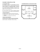
PLANNING YOUR INSTALLATION COMBUSTIBLE WALL CLEARANCES Corner Installation WARNING: IT IS VERY IMPORTANT THAT YOU OBSERVE THE MINIMUM CLEARANCES. There are listed clearances for your stove which were determined in a Laboratory test using various "classes" of stove pipe or chimney. Minimums are first established for the stove itself and increased based on how much heat is transferred by each class of pipe.
PLANNING YOUR INSTALLATION ALCOVE CLEARANCES NOTE:" = inches, mm = millimeter, cm = centimeter Alcoves must have minimum dimensions of 84" (214 cm) height, 56" (142 cm) width and 24" (610 mm) maximum depth. Require pipe: Type L Vent pipe to the top of the stove.
INSTALLATION AIR INTAKE COVER The pedestal is equipped with an air intake cover (located at the top front of the pedestal). The air intake cover should be adjusted to the open position if outside combustion air is NOT provided. If outside combustion air is provided, adjust to the closed position (see illustration to the right). NOTE: Because the base sits 1” (25.
INSTALLATION SECURING THE STOVE TO THE FLOOR Manufactured (Mobile) Homes Only Once the outside air floor duct is in position, replace the floor protector. Make sure that the floor protector's hole is aligned with the outside air opening. Next position and align the stove on the hearth pad. Manufactured (mobile) home installations require that the stove be secured to the floor. This ensures that the stove will not shift when the manufactured (mobile) home is moved.
INSTALLATION CHIMNEY INSPECTION Existing chimneys must be inspected before installing your stove. Consult your local building department for chimney code requirements. A masonry chimney must have a code approved liner. This liner must not have broken or missing pieces. Some non-code masonry chimneys may be brought up to code by being relined. (Consult your dealer or qualified chimney sweep).
INSTALLATION DRAFT REQUIREMENTS The appliance is merely one component of a larger system. The other equally important component is the venting system which is necessary for achieving the required flow of combustion air to the fire chamber and for safely removing unwanted combustion byproducts from the appliance. If the venting system's design does not promote these ends, the system may not function properly. Poorly functioning venting systems may create performance problems (i.e.
INSTALLATION See Pipe Manufacturers Instructions For Installation Requirements Of Venting Components And Vent Clearances. MANUFACTURED (MOBILE) HOME STANDARD Using 6” (152 mm) Diameter Type L-Vent Connector Pipe RESIDENTIAL STANDARD Using 6” (152 mm) Diameter Single Wall Connector Pipe. Not Approved For Manufactured (Mobile) Homes. Spark Arrestor Cap Chimney Termination Cap 3 ft. (915 mm) Minimum Storm Collar Storm Collar Flashing Roof Flashing Ceiling Support Assembly 14.5” (369 mm) Minimum 1215 ft.
INSTALLATION - Combustible Wall Chimney Connector Pass-Throughs A Min. Chimney Clearance to Brick & Combustibles – 2 in. (50.8mm) Chimney Flue Min. Clearance 12 in. (304.8mm) of Brick Chimney Connector Min. 12 in. (304.8mm) to Combustibles B Fire Clay Liner Min. Chimney Clearance from Masonry to Sheet Steel Supports & Combustibles – 2 in. (50.8mm) Nonsoluble Refractory Cement Min. Clearance 9 in. (228.
CARE AND OPERATI0N ASH DRAWER The large ash drawer located on the left side of the pedestal is designed to make cleaning easier by containing the ashes in a removable drawer. Secondary Air Tube Bypass Damper Control Tunnel Baffle Positioning Stops Damper Door Ash Drawer Catalytic Combustor WARNING: DO NOT OPERATE THIS STOVE WITHOUT THE ASH DRAWER PROPERLY INSTALLED AND SECURED (SEALED), AS THIS WILL PRODUCE EXTREME TEMPERATURES, RESULTING IN OVERFIRING.
CARE AND OPERATION FUEL DOOR The gold or black door option is purchased separately, but is required. Install the door per instructions provided in kit (see page 28 for ordering information). WARNING: DO NOT OPERATE THIS STOVE WITHOUT THE DOOR PROPERLY INSTALLED AND SECURED AS THIS WILL PRODUCE EXTREME TEMPERATURES (OVERFIRING). THE DOOR AND GLASS GASKETS PROVIDE IMPORTANT SEALS, AND MUST BE MAINTAINED (SEE MAINTENANCE REQUIREMENTS ON PAGE 19).
CARE AND OPERATION BREAK-IN PERIOD Your stove finish is a high temperature paint that requires time and temperature to completely cure. We recommend that you ventilate the house during the initial burns. The paint emits non-toxic odors during this process. KEEP YOUR HOUSE WELL VENTILATED DURING THE CURING PROCESS TO PREVENT ACTIVATION OF YOUR HOME SMOKE DETECTOR. The paint manufacturer recommends three burn cycles to cure the paint. The first two burns should be low heat, approximately 250° F.
CARE AND OPERATION FUEL REFUELING To refuel the stove, open the bypass damper and move the primary air control to "HIGH." Let the fire "LIVEN UP" for about one minute. Open the fuel door about ½” (1 cm) and hold in this position about 30 seconds or until the stove is drafting well. Open the door and add wood.
FUEL MAINTENANCE SEASONING GUIDE Softwoods – 6 months to 18 months Hardwoods – 12 months to 24 months ASH REMOVAL AND DISPOSAL Logs that are 5” (127 mm) diameter across or larger should be split in half, three pieces if over 8” (203 mm), and four pieces when over a foot (305 mm) across. If the tree was fell 2 to 4 years ago, it still needs to be cut, split, and seasoned for 6 to 24 months depending on the wood.
MAINTENANCE DOOR / GLASS GASKET AND ASH DRAWER GASKET A 3/4" (19 mm) spun fiberglass gasket provides the seal around the fuel door and a 1/8” (3.2 mm) x 1” (25.4 mm) flat woven gasket glass provides the seal around the glass. A ½” (13 mm) flat fiberglass gasket provides the seal around the ash drawer. Should these gaskets become frayed or damaged, they should be replaced with the same size and type as the original gasket. Contact your dealer for ordering.
MAINTENANCE CATALYST REPLACEMENT The normal expected life of a catalyst (catalytic combustor) is 10,000 to 12,000 hours if the appliance is operated correctly and proper fuels are used. If the catalyst has been deactivated, it should be replaced. Symptoms of deactivation include – noticeably darker smoke exiting chimney and less heat output.
TROUBLESHOOTING SMOKES OUT FUEL DOOR WHEN OPEN (see ✸) 1. The primary air control is closed. 2. The chimney is too cool. Set the primary air control on "HIGH" with the bypass damper control "OPEN" for a few minutes before opening the fuel door. 3. Excess creosote will not only restrict your draft but it will create a risk of a creosote fire. Strictly adhere to maintenance requirements as outlined in this manual.
TROUBLESHOOTING 2. Metal flue assembled improperly. Top flue sections should be inserted into lower flue sections. CATALYST PLUGGING 1. Burning materials that produce a lot of char and fly ash. Do not burn materials such as garbage, gift wrap, cardboard, etc. 2. Burning wet pitchy woods or burning large loads of small diameter wood with the combustor in the operation position (without light-off taking place). Burn proper fuel only.
TROUBLESHOOTING OVERFIRING DAMAGE If the heater or chimney connector glows, the appliance is overfiring. Other symptoms may include: Cracking, warping or burning out of components, catalytic combustor may deteriorate, gold doors may turn color, stove glass may develop a haze which will not come off with cleaning, firebox baffle plate (tunnel baffle) may warp, etc. Overfiring of a stove is a condition where excessive temperatures are reached, beyond the design capabilities of the appliance.
SPECIFICATIONS: Model 1003C Maximum Log Length Manufactured (Mobile) Home Approved Side View 18” (458 mm) Yes, U.S.A. and Canada Outside Air Provision Yes Flue Collar Size 6” (153 mm) Flue Position Top Stove Back to Flue Center 9” (229 mm) Width 25.25” (642 mm) Depth 27” (686 mm) Height (to flue) 34.5” (877 mm) Height 32.5” (826 mm) Approx. Burn Time 8 - 12 hours Fuel Capacity 50 – 70 lbs.
REPLACEMENT PARTS LIST: Model 1003C ITEM NO DESCRIPTION Door Parts 27M65 Clip Kit, Glass G6000 Door Assembly, Black, H0533 (handle included) 14M72 Door Assembly, Gold, G3000 (handle included) 86-128 Gasket Kit, Door (3/4" rope, includes adhesive) 27M81 Gasket Kit, Glass (10' of 10580.
REPLACEMENT PARTS LIST: Model 1003C Cat. No. Model Description / Part No.
COMPONENT DIAGRAMS - Model 1003C Air Intake Draft Module Catalytic Combustor System Components Secondary Air Tube Bypass Damper Control Tunnel Baffle Positioning Stops Damper Door Door Assembly Catalytic Combustor Catalyic Combustor Retainer Clip Damper Assembly Setscrews Bypass Damper Control Rod Handle Assembly (P/N LB-102214) Damper Blade Assembly (Linkage) Nut Torque Plate Damper Door Handle Rod Washers Coil Handle PAGE 27
OPTIONAL ACCESSORIES - Model 1003C Note: Install and use accessories per instructions provided with the accessory kit. Outside Air Floor Duct (OAFD-S) Catalog # Model Description 14M67 * 14M72 * H0533 14M22 14M21 70K99 Outside Air Floor Duct Gold Door Kit Black Door Kit Blower Kit Stove Stat Kit Touch-up Spray Paint Kit, Black (12 oz spray can) OAFD-S DK100-G DK100-B BK-100 SSK TSPK-B Outside air can be delivered for combustion air by utilizing this floor penetration duct.
SAFETY/LISTING LABEL PAGE 29
EPA LABEL PAGE 30
OWNERSHIP RECORDS Dealer’s Name: Dealer’s Address: City: State: Zip Code: Serial Number: Date of Purchase: Date Installed: Notes: SERVICE AND MAINTENANCE LOG Service Service Service Date Technician Description Page 31
1110 West Taft Avenue Orange, CA 92865