Lenovo A7600 Hardware Maintenance Manual
Note: Before using this information and the product it supports, be sure to read the general information under “Notices” on page 78. First Edition (February 2014) © Copyright Lenovo 2014. All rights reserved. LENOVO products, data, computer software, and services have been developed exclusively at private expense and are sold to governmental entities as commercial items as defined by 48 C.F.R. 2.101 with limited and restricted rights to use, reproduction and disclosure.
Contents About this manual........................................iv Safety information.........................................1 General safety ...................................................... 2 Electrical safety .................................................... 3 Safety inspection guide ...................................... 5 Handling devices that are sensitive to electrostatic discharge .................................................... 6 Grounding requirements ...............................
About this manual This manual contains service and reference information for the following Lenovo product: • Lenovo A7600 Use this manual to troubleshoot problems. The manual is divided into the following sections: • The common sections provide general information, guidelines, and safety information required for servicing computers. • The product-specific section includes service, reference, and product-specific parts information.
Safety information Safety information This chapter presents the following safety information that you need to get familiar with before you service a Lenovo computer: • “General safety” on page 2 • “Electrical safety” on page 3 • “Safety inspection guide” on page 5 • “Handling devices that are sensitive to electrostatic discharge” on page 6 • “Grounding requirements” on page 6 • “Safety notices: multilingual translations” on page 7 • “Laser compliance statement” on page 14 1
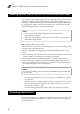
Lenovo A7600 Hardware Maintenance Manual General safety Follow these rules below to ensure general safety: • Observe a good housekeeping in the area where the machines are put during and after the maintenance. • When lifting any heavy object: 1. Make sure that you can stand safely without slipping. 2. Distribute the weight of the object equally between your feet. 3. Use a slow lifting force. Never move suddenly or twist when you attempt to lift it. 4.
Safety information Electrical safety Observe the following rules when working on electrical equipments. Important: Use only approved tools and test equipments. Some hand tools have handles covered with a soft material that does not insulate you when working with live electrical currents. Many customers have rubber floor mats near their machines that contain small conductive fibers to decrease electrostatic discharges. Do not use such kind of mat to protect yourself from electrical shock.
Lenovo A7600 Hardware Maintenance Manual • Always look carefully for possible hazards in your work area. Examples of these hazards are moist floors, nongrounded power extension cables, power surges, and missing safety grounds. • Do not touch live electrical circuits with the reflective surface of a plastic dental mirror. The surface is conductive; such touching can cause personal injury and machine damage.
Safety information Safety inspection guide The purpose of this inspection guide is to assist you in identifying potential unsafe conditions. As each machine was designed and built, required safety items were installed to protect users and service personnel from injury. This guide addresses only those items. You should use good judgment to identify potential safety hazards according to the attachment of non-Lenovo features or options not covered by this inspection guide.
Lenovo A7600 Hardware Maintenance Manual Handling devices that are sensitive to electrostatic discharge Any computer part containing transistors or integrated circuits (ICs) should be considered sensitive to electrostatic discharge (ESD). ESD damage can occur when there is a difference in charge between objects. Protect against ESD damage by equalizing the charge so that the machine, the part, the work mat, and the person handling the part are all at the same charge. Notes: 1.
Safety information Safety notices: multilingual translations The safety notices in this section are provided in English, French, German, Hebrew, Italian, Japanese, and Spanish. Safety notice 1 Before the computer is powered on after FRU replacement, make sure all screws, springs, and other small parts are in place and are not left loose inside the computer. Verify this by shaking the computer and listening for rattling sounds. Metallic parts or metal flakes can cause electrical shorts.
Lenovo A7600 Hardware Maintenance Manual Safety notice 2 DANGER Some standby batteries contain a small amount of nickel and cadmium. Do not disassemble a standby battery, recharge it, throw it into fire or water, or short-circuit it. Dispose of the battery as required by local ordinances or regulations. Use only the battery in the appropriate parts listing. Use of an incorrect battery can result in ignition or explosion of the battery. Certaines batteries de secours contiennent du nickel et du cadmium.
Safety information Safety notice 3 DANGER The battery pack contains small amounts of nickel. Do not disassemble it, throw it into fire or water, or short-circuit it. Dispose of the battery pack as required by local ordinances or regulations. Use only the battery in the appropriate parts listing when replacing the battery pack. Use of an incorrect battery can result in ignition or explosion of the battery. La batterie contient du nickel. Ne la démontez pas, ne l’exposez ni au feu ni à l’eau.
Lenovo A7600 Hardware Maintenance Manual Safety notice 4 DANGER The lithium battery can cause a fire, an explosion, or a severe burn. Do not recharge it, remove its polarized connector, disassemble it, heat it above 100°C (212°F), incinerate it, or expose its cell contents to water. Dispose of the battery as required by local ordinances or regulations. Use only the battery in the appropriate parts listing. Use of an incorrect battery can result in ignition or explosion of the battery.
Safety information Safety notice 5 If the LCD breaks and the fluid from inside the LCD gets into your eyes or on your hands, immediately wash the affected areas with water at least for 15 minutes. Seek medical care if any symptoms caused by the fluid are present after washing. Si le panneau d’affichage à cristaux liquides se brise et que vous recevez dans les yeux ou sur les mains une partie du fluide, rincez-les abondamment pendant au moins quinze minutes.
Lenovo A7600 Hardware Maintenance Manual Safety notice 6 DANGER To avoid shock, do not remove the plastic cover that protects the lower part of the inverter card. Afin d’éviter tout risque de choc électrique, ne retirez pas le cache en plastique protégeant la partie inférieure de la carte d’alimentation. Aus Sicherheitsgründen die Kunststoffabdeckung, die den unteren Teil der Spannungswandlerplatine umgibt, nicht entfernen.
Safety information Safety notice 8 DANGER Before removing any FRU, turn off the computer, unplug all power cords from electrical outlets, remove the battery pack, and then disconnect any interconnecting cables. Avant de retirer une unité remplaçable en clientèle, mettez le système hors tension, débranchez tous les cordons d’alimentation des socles de prise de courant, retirez la batterie et déconnectez tous les cordons d’interface.
Lenovo A7600 Hardware Maintenance Manual Laser compliance statement Some models of Lenovo computer are equipped from the factory with an optical storage device such as a CD-ROM drive or a DVD-ROM drive. Such devices are also sold separately as options. If one of these drives is installed, it is certified in the U.S. to conform to the requirements of the Department of Health and Human Services 21 Code of Federal Regulations (DHHS 21 CFR) Subchapter J for Class 1 laser products.
Safety information A CD-ROM drive, a DVD-ROM drive, or any other storage device installed may contain an embedded Class 3A or Class 3B laser diode. Note the following: DANGER Emits visible and invisible laser radiation when open. Do not stare into the beam, do not view directly with optical instruments, and avoid direct exposure to the beam. Radiação por raio laser ao abrir. Não olhe fixo no feixe de luz, não olhe diretamente por meio de instrumentos óticos e evite exposição direta com o feixe de luz.
Lenovo A7600 Hardware Maintenance Manual Important service information This chapter presents the following important service information: • “Strategy for replacing FRUs” on page 16 — “Important notice for replacing a system board” on page 17 • “Important information about replacing RoHS compliant FRUs” on page 18 Important: BIOS and device driver fixes are customer-installable. The BIOS and device drivers are posted on the customer support site: http://consumersupport.lenovo.com/.
Important service information Important notice for replacing a system board Some components mounted on a system board are very sensitive. Improper handling can cause damage to those components, and may cause a system malfunction. Attention: When handling a system board: • Do not drop the system board or apply any excessive force to it. • Avoid rough handling of any kind. • Avoid bending the system board and hard pushing to prevent cracking at each BGA (Ball Grid Array) chipset.
Lenovo A7600 Hardware Maintenance Manual Important information about replacing RoHS compliant FRUs RoHS, The Restriction of Hazardous Substances in Electrical and Electronic Equipment Directive (2002/95/EC) is a European Union legal requirement affecting the global electronics industry. RoHS requirements must be implemented on Lenovo products placed on the market after June 2006. Products on the market before June 2006 are not required to have RoHS compliant parts.
General checkout General checkout This chapter presents the following information: • “What to do first” on page 20 • “Power system checkout” on page 21 Before you go to the checkout, make sure to read the following important notes: Important notes: • Only certified trained personnel can service the computer. • Before replacing any FRU, read the entire page on removing and replacing FRUs. • When you replace FRUs, use new nylon-coated screws.
Lenovo A7600 Hardware Maintenance Manual What to do first When you do return an FRU, you must include the following information in the parts exchange form or parts return form that you attach to it: 1. Name and phone number of servicer 2. Date of service 3. Date on which the machine failed 4. Date of purchase 5. Procedure index and page number in which the failing FRU was detected 6. Failing FRU name and part number 7. Machine type, model number, and serial number 8.
General checkout Power system checkout To verify a symptom, follow the steps below: 1. Turn off the computer. 2. Remove the battery pack. 3. Connect the AC adapter. 4. Make sure that power is supplied when you turn on the computer. 5. Turn off the computer. 6. Disconnect the AC adapter and install the charged battery pack. 7. Make sure that the battery pack supplies power when you turn on the computer.
Lenovo A7600 Hardware Maintenance Manual Checking the internal battery status To check the battery status of the tablet, do either of the following: • Approximate information about the battery status Get the approximate status of the battery at any time by checking the battery status icon on the system bar in the upper-right corner of the screen. The shorter the green bar is, the less the battery power remains.
Related service information Related service information This chapter presents the following information: • “Security” on page 23 • “Power management” on page 23 Security Security settings include: SCREEN SECURITY, SIM CARD LOCK (3G version only), PASSWORDS, DEVICE ADMINISTRATION and CREDENTIAL STORAGE. Power management Note: Power management modes are not supported for APM operating system.
Lenovo A7600 Hardware Maintenance Manual Lenovo A7600 This chapter presents the following product-specific service references and product-specific parts information: • “Specifications” on page 24 • “FRU replacement notices” on page 26 • “Removing and replacing an FRU” on page 27 • “Locations” on page 73 • “Parts list” on page 75 Specifications The following table lists the specifications of the Lenovo A7600 tablet. Table 1. Specifications Feature Description Size & Weight Size • 264.10mm x 176.
Lenovo A7600 Ports • • • • Micro-USB (USB 2.0), 5-pin Earphone, 3.5mm SIM card slot T-flash card slot • • • • • • WiFi, 802.11b/g/n WiFi Direct WiFi display A-GPS (10s fast positioning) Bluetooth 4.
Lenovo A7600 Hardware Maintenance Manual FRU replacement notices This section presents notices related to removing and replacing parts. Read this section carefully before replacing any FRU. Screw notices Loose screws can cause a reliability problem. In Lenovo computers, this problem is addressed with special nylon-coated screws that have the following characteristics: • They maintain tight connections. • They do not easily come loose, even with shock or vibration. • They are harder to tighten.
Lenovo A7600 Removing and replacing an FRU This section presents exploded figures with the instructions to indicate how to remove and replace the FRU. Make sure to observe the following general rules: 1. Do not attempt to service any computer unless you have been trained and certified. An untrained person runs the risk of damaging parts. 2. Before replacing any FRU, review “FRU replacement notices” on page 26. 3. Begin by removing any FRUs that have to be removed before the failing FRU.
Lenovo A7600 Hardware Maintenance Manual 1010 Rear cover and side keys 1. Open the card slot cover of the tablet using a guitar pick. Figure 1-1. Opening the card slot cover 2. Remove screw a in the card slot recess. Figure 1-2. The screw in the card slot recess 28 Part No.
Lenovo A7600 Note: The screw is sealed by the manufacturer for checking the warranty qualification of the product. 3. Hold the tablet in one hand and use a guitar pick to unlock the rear cover from the tablet along the joint line as shown in the figure below. Figure 1-3.
Lenovo A7600 Hardware Maintenance Manual CAUTION: Handle with care! The rear cover can be damaged at its four corners! Do not cut into the corners of the rear cover using the guitar pick or try to lift the rear cover off the tablet when the locks near the corners have not been disengaged. 4. Remove the rear cover. Figure 1-4.
Lenovo A7600 5. Detach the power key from the rear cover using a pair of tweezers. Figure 1-5. Detaching the power key 6. Remove the power key Figure 1-6.
Lenovo A7600 Hardware Maintenance Manual 7. Detach the volume key from the rear cover using a pair of tweezers. Figure 1-7. Detaching the volume key 8. Remove the volume key. Figure 1-8.
Lenovo A7600 1020 Battery pack For access, remove the following FRUs: • “1010 Rear cover and side keys” on page 28 CAUTION: Risk of explosion if the battery is replaced with an incorrect type. When replacing the lithium battery, use only the same or an equivalent type that is recommended by the manufacturer. The battery contains lithium and can explode if not properly used, handled, or disposed of. Dispose of the used battery according to the instructions.
Lenovo A7600 Hardware Maintenance Manual 2. Detach the battery pack from its seat by inserting a thin flat blade into the joint surface and then cutting along the joint line in the direction shown in the figure below. Figure 2-2. Detaching the battery pack 3. Remove the battery pack from the front module of the tablet. Figure 2-3.
Lenovo A7600 1030 Battery holder For access, remove the following FRUs in order: • “1010 Rear cover and side keys” on page 28 • “1020 Battery pack” on page 33 1. Peel off the conductive fabrics on the battery holder as shown in the figure below. Figure 3-1. The conductive fabrics on the battery holder 2. Remove screws a on the battery holder. Figure 3-2.
Lenovo A7600 Hardware Maintenance Manual Part No. Screw (quantity) Color Torque a Phillips flat head screw (4) Silver N/A 3. Remove the battery holder from the front module of the tablet. Figure 3-3.
Lenovo A7600 1040 LCM FPC For access, remove the following FRUs in order: • “1010 Rear cover and side keys” on page 28 • “1020 Battery pack” on page 33 • “1030 Battery holder” on page 35 1. Peel off the mylar on the LCM FPC connector on the main board. Figure 4-1. Peeling off the mylar 2. Unlock the above-mentioned LCM FPC connector using a guitar pick or a thin flat blade. Figure 4-2.
Lenovo A7600 Hardware Maintenance Manual 3. Pull out the LCM FPC from the unlocked connector using a pair of tweezers. Figure 4-3. Pulling out the LCM FPC 4. Peel off the mylar on the LCM FPC connector on the front module. Figure 4-4.
Lenovo A7600 5. Unlock the LCM FPC connector mentioned in Step 4 using a guitar pick or a thin flat blade. Figure 4-5.
Lenovo A7600 Hardware Maintenance Manual 6. Pull out the LCM FPC from the unlocked connector using a pair of tweezers. Figure 4-6. Pulling out the LCM FPC The LCM FPC is now removed.
Lenovo A7600 1050 Rear camera For access, remove the following FRUs in order: • “1010 Rear cover and side keys” on page 28 • “1020 Battery pack” on page 33 1. Detach the FPC of the rear camera from its connector on the main board using a thin flat blade or guitar pick. Figure 5-1.
Lenovo A7600 Hardware Maintenance Manual 2. Remove the rear camera from the tablet. Figure 5-2.
Lenovo A7600 1060 Antenna and CAP sensor FPC assembly For access, remove the following FRUs in order: • “1010 Rear cover and side keys” on page 28 • “1020 Battery pack” on page 33 1. Peel off the mylar on the CAP sensor FPC connector that is located on the main board. Figure 6-1. Peeling off the mylar on the CAP sensor FPC connector 2. Unlock the CAP sensor FPC connector using a guitar pick. Figure 6-2.
Lenovo A7600 Hardware Maintenance Manual 3. Pull out the CAP sensor FPC from its connector using a pair of tweezers. Figure 6-3. Pulling out the CAP sensor FPC 4. Remove screw a under the disconnected end of the CAP sensor FPC. Figure 6-4. The screw under the CAP sensor FPC 44 Part No.
Lenovo A7600 5. Peel off the other end of the CAP sensor FPC from the antenna box. Figure 6-5. Peeling off the other end of the CAP sensor FPC 6. Remove screw a under the peeled-off end of the CAP sensor FPC. Figure 6-6. The screw under the CAP sensor FPC Part No.
Lenovo A7600 Hardware Maintenance Manual 7. Detach the RF cable from its connector on the main board using a guitar pick. Figure 6-7. Detaching the RF cable 8. Take out the RF cable from the cable duct in the front module of the tablet. Figure 6-8.
Lenovo A7600 9. Peel off the conductive fabric (shown in figure below) of the antenna from the battery holder. Figure 6-9.
Lenovo A7600 Hardware Maintenance Manual 10. Slowly remove the antenna and CAP sensor FPC assembly from the front module while keeping its conductive fabric clear of the cables of the right speaker. Figure 6-10. Removing the antenna and CAP sensor FPC assembly The antenna and CAP sensor FPC assembly is now removed.
Lenovo A7600 1070 SIM board FPC For access, remove the following FRUs in order: • “1010 Rear cover and side keys” on page 28 • “1020 Battery pack” on page 33 1. Peel off the mylar on the SIM board FPC connector on the SIM board. Figure 7-1. Peeling off the mylar at the SIM board end 2. Unlock the above-mentioned SIM board FPC connector using a guitar pick or a thin flat blade. Figure 7-2.
Lenovo A7600 Hardware Maintenance Manual 3. Peel off the mylar on the SIM board FPC connector on the main board. Figure 7-3. Peeling off the mylar at the main board end 4. Unlock the SIM board FPC connector on the main board using a guitar pick or a thin flat blade. Figure 7-4.
Lenovo A7600 5. Pull out the SIM board FPC from both connectors using a pair of tweezers. Figure 7-5. Pulling out the SIM board FPC The SIM board FPC is now removed.
Lenovo A7600 Hardware Maintenance Manual 1080 SIM board Important notices for handling PCB: When handling PCB, bear the following in mind: • Be careful not to drop the PCB onto a bench top that has a hard surface, such as surface made of metal, wood, or composite materials. • Avoid rough handling of any kind. • Make sure not to drop or stack the PCB in the whole process. • Make sure to put the PCB only on surface covered with such materials as an ESD mat or conductive corrugated plate.
Lenovo A7600 2. Remove the SIM board. Figure 8-2.
Lenovo A7600 Hardware Maintenance Manual 1090 Main board Important notices for handling PCB: When handling PCB, bear the following in mind: • Be careful not to drop the PCB onto a bench top that has a hard surface, such as surface made of metal, wood, or composite materials. • Avoid rough handling of any kind. • Make sure not to drop or stack the PCB in the whole process. • Make sure to put the PCB only on surface covered with such materials as an ESD mat or conductive corrugated plate.
Lenovo A7600 2. Unlock the TP FPC connector using a guitar pick. Figure 9-2. Unlocking the TP FPC connector 3. Pull out the TP FPC from its connector using a pair of tweezers. Figure 9-3.
Lenovo A7600 Hardware Maintenance Manual 4. Desolder the wires of the vibrator motor from the main board at the position shown in the figure below. Figure 9-4.
Lenovo A7600 5. Desolder the wires of the left speaker from the main board at the position shown in the figure below. Figure 9-5.
Lenovo A7600 Hardware Maintenance Manual 6. Desolder the wires of the right speaker from the main board at the position shown in the figure below. Figure 9-6.
Lenovo A7600 7. Remove screws a on the main board. Figure 9-7. The screws on the main board Part No. Screw (quantity) Color Torque a Silver N/A Phillips flat head screw (4) 8. Release the main board from the lock at the position shown in the figure below. Figure 9-8.
Lenovo A7600 Hardware Maintenance Manual 9. Release the main board from another lock at the position shown in the figure below. Figure 9-9.
Lenovo A7600 10. Lift the main board on the top side and then remove it from the front module in the direction shown in the figure below. Figure 9-10.
Lenovo A7600 Hardware Maintenance Manual 11. Turn over the main board and then peel off the mylar on FPC connector of the front camera. Figure 9-11. Peeling off the mylar on the FPC connector 12. Unlock the FPC connector of the front camera using a guitar pick. Figure 9-12.
Lenovo A7600 13. Pull out the front camera from its connector using a pair of tweezers. Figure 9-13. Pulling out the front camera The main board is now separated from other components and removed from the tablet.
Lenovo A7600 Hardware Maintenance Manual 1100 Front camera The procedure for removing the front camera is the same as that of the main board. Please refer to “1090 Main board” on page 54.
Lenovo A7600 1110 Vibrator motor For access, remove the following FRUs in order: • “1010 Rear cover and side keys” on page 28 • “1020 Battery pack” on page 33 1. Desolder the wires of the vibrator motor as described in Step 4 on page 56 in “1090 Main board”. 2. Detach the vibrator motor from its seat on the front module of the tablet using a thin flat blade. Figure 11-1 Detaching the vibrator motor 3. Remove the vibrator motor.
Lenovo A7600 Hardware Maintenance Manual 1120 Left speaker For access, remove the following FRUs in order: • “1010 Rear cover and side keys” on page 28 • “1020 Battery pack” on page 33 • “1030 Battery holder” on page 35 • “1040 LCM FPC” on page 37 • “1070 SIM board FPC” on page 49 • “1080 SIM board” on page 52 and Detach the following FRUs in order: • Rear camera (see Step 1 in “1050 Rear camera” on page 41) • Antenna and CAP sensor FPC assembly (see Step 1 to 3 and Step 7 in “1060 Antenna and CAP sensor F
Lenovo A7600 2. Detach the left speaker from its seat on the front module of the tablet using a thin flat blade. Figure 12-2 Detaching the left speaker 3. Slowly pull out the wires of the left speaker through the hole in the front module.
Lenovo A7600 Hardware Maintenance Manual 4. Remove the left speaker.
Lenovo A7600 1130 Right speaker For access, remove the following FRUs in order: • “1010 Rear cover and side keys” on page 28 • “1020 Battery pack” on page 33 • “1030 Battery holder” on page 35 • “1040 LCM FPC” on page 37 • “1070 SIM board FPC” on page 49 • “1080 SIM board” on page 52 and Detach the following FRUs in order: • Rear camera (see Step 1 in “1050 Rear camera” on page 41) • Antenna and CAP sensor FPC assembly (see Step 1 to 3 and Step 7 in “1060 Antenna and CAP sensor FPC assembly” on page 43) •
Lenovo A7600 Hardware Maintenance Manual Figure 13-1 Taking out the wires from the wire duct 2. Remove the glue that is used to fix the wires of the right speaker using a thin flat blade.
Lenovo A7600 3. Detach the right speaker from its seat on the front module of the tablet using a thin flat blade. Figure 13-3 Detaching the right speaker 4. Slowly pull out the wires of the right speaker through the hole in the front module.
Lenovo A7600 Hardware Maintenance Manual 5. Remove the right speaker.
Lenovo A7600 Locations Front view Left speaker Front camera Right speaker 73
Lenovo A7600 Hardware Maintenance Manual Rear view Microphone Rear camera Power key Volume key Earphone socket Micro-USB connection SIM card slot T-flash card slot 74
Lenovo A7600 Parts list This section presents the following service parts: • “Overall” on page 75 • “Screw” on page 77 Overall 75
Lenovo A7600 Hardware Maintenance Manual Table 1. Parts list–Overall No. FRU FRU No.
Lenovo A7600 Screw Table 2.
Lenovo A7600 Hardware Maintenance Manual Notices Lenovo may not offer the products, services, or features discussed in this document in all countries. Consult your local Lenovo representative for information on the products and services currently available in your area. Any reference to a Lenovo product, program, or service is not intended to state or imply that only that Lenovo product, program, or service may be used.
Notices Any performance data contained herein was determined in a controlled environment. Therefore, the result obtained in other operating environments may vary significantly. Some measurements may have been made on development-level systems and there is no guarantee that these measurements will be the same on generally available systems. Furthermore, some measurements may have been estimated through extrapolation. Actual results may vary.