Hardware Replacement Guide Lenovo 3000 J Series Types 8252, 8253, 8254, 8257, 8258, 8259
Lenovo 3000 J Series
First Edition (December 2005) © Copyright Lenovo 2005. Portions © Copyright International Business Machines Corporation 2005. All rights reserved. U.S. GOVERNMENT USERS – RESTRICTED RIGHTS: Our products and/or services are provided with RESTRICTED RIGHTS.
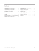
Contents Overview . . . . . . . . . . . . . . v Chapter 2. Replacing hardware . . . . . 7 Safety information for replacing CRUs . . . . . . v Safety information for replacing FRUs . . . . . . v Additional information resources . . . . . . . v Tools required . . . . . . . . . . . . . vi Handling static-sensitive devices . . . . . . . vi Removing the cover . . . . . . . . . . . . 7 Replacing a memory module . . . . . . . . . 8 Replacing a PCI adapter . . . . . . . . . . 9 Replacing a keyboard . . . . . . .
iv Hardware Replacement Guide
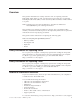
Overview This guide is intended to be used by customers who are replacing Customer Replaceable Units (CRUs) as well as trained service personnel who are replacing Field Replaceable Units (FRUs). In this document, CRUs and FRUs will be referred to as parts. Note: Trained service personnel should refer to the Hardware Maintenance Manual(HMM) for parts ordering information.″ This guide does not include procedures for all parts.
Tools required To replace some parts in your computer, you might need a flat-blade or Phillips screwdriver. Additional tools might be needed for certain parts. Handling static-sensitive devices Static electricity, although harmless to you, can seriously damage computer components and parts. When replacing a part, do not open the static-protective package containing the new part until the defective part has been removed from the computer and you are ready to install the new part.
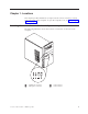
Chapter 1. Locations This chapter provides illustrations to help locate the various connectors, controls and components of the computer. To open the computer cover, see “Removing the cover” on page 7. Locating the connectors on the front of your computer The following illustration shows the location of connectors on the front of the computer. 1 2 Headphone connector Microphone connector © Lenovo 2005. Portions © IBM Corp. 2005.
Locating the connectors on the rear of your computer The following illustration shows the location of connectors on the rear of the computer.
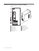
Locating components The following illustration will help you locate the various components in your computer. 1 Microprocessor and heat sink 2 Memory modules 3 AGP connector 4 PCI connectors 5 PCI adapter 6 Power supply Chapter 1.
Identifying parts on the system board The system board (sometimes called the planar or motherboard) is the main circuit board in your computer. It provides basic computer functions and supports a variety of devices. The following illustration shows the locations of parts on the system board for some models.
The following illustration shows the locations of parts on the system board for some models.
6 Hardware Replacement Guide
Chapter 2. Replacing hardware Attention Do not open your computer or attempt any repair before reading the “Important safety information” in the Quick Reference that was included with your computer or in the Hardware Maintenance Manual (HMM) for the computer. To obtain copies of the Quick Reference or HMM, go to http://www.lenovo.com/support. Note: Use only the parts provided by Lenovo.
4. Remove the two screws at the rear of the left side cover and slide the cover to the rear to remove. Replacing a memory module Attention Do not open your computer or attempt any repair before reading the “Important safety information” in the Quick Reference that was included with your computer or in the Hardware Maintenance Manual (HMM) for the computer. To obtain copies of the Quick Reference or HMM, go to http://www.lenovo.com/support.
2. Remove the memory module being replaced by opening the retaining clips as shown. 3. Position the replacement memory module over the memory connector. Make sure that the notch 1 on the memory module aligns correctly with the connector key 2 on the system board. Push the memory module straight down into the memory connector until the retaining clips close. 4. Go to “Completing the parts replacement” on page 12.
This section provides instructions on how to replace a PCI adapter. 1. Remove the computer cover. See “Removing the cover” on page 7. 2. Remove screw from adapter. 3. Remove the adapter by pulling it straight out of the adapter connector. 4. Remove the new adapter from its static-protective package. 5. Install the new adapter into the appropriate slot on the system board. 6. Secure adapter with the screw as shown. 7. Go to “Completing the parts replacement” on page 12.
3. Locate the keyboard connector. Note: Your keyboard might be connected to a standard keyboard connector 1 or a USB connector 2 . Depending on where your keyboard is connected, see “Locating the connectors on the rear of your computer” on page 2 or “Locating the connectors on the front of your computer” on page 1. 4. Disconnect the failing keyboard cable from the computer. 5. Connect the new keyboard to the appropriate connector on the computer. 6. Go to “Completing the parts replacement” on page 12.
5. Connect the new mouse to the appropriate connector on the computer. 6. Go to “Completing the parts replacement.” Completing the parts replacement After working with parts, you need to replace the computer cover and reconnect any cables, including telephone lines and power cords. Also, depending on the part that was replaced, you might need to confirm the updated information in the Setup Utility program. 1.
Appendix. Notices Lenovo may not offer the products, services, or features discussed in this document in all countries. Consult your local Lenovo representative for information on the products and services currently available in your area. Any reference to a Lenovo product, program, or service is not intended to state or imply that only that Lenovo product, program, or service may be used.
vary significantly. Some measurements may have been made on development-level systems and there is no guarantee that these measurements will be the same on generally available systems. Furthermore, some measurements may have been estimated through extrapolation. Actual results may vary. Users of this document should verify the applicable data for their specific environment. Television output notice The following notice applies to models that have the factory-installed television-output feature.
Part Number: 41T3793 Printed in USA (1P) P/N: 41T3793