ThinkCentre M79 User Guide Machine Types: 10CN, 10CQ, 10CR, and 10CS
Note: Before using this information and the product it supports, be sure to read and understand the “Read this first: Important safety information” on page v and Appendix F “Notices” on page 131. First Edition (July 2014) © Copyright Lenovo 2014. LIMITED AND RESTRICTED RIGHTS NOTICE: If data or software is delivered pursuant a General Services Administration “GSA” contract, use, reproduction, or disclosure is subject to restrictions set forth in Contract No. GS-35F-05925.
Contents Read this first: Important safety information . . . . . . . . . . . . . . . v Before using this manual. . . . . Service and upgrades . . . . . . Static electricity prevention . . . . Power cords and power adapters . Extension cords and related devices Plugs and outlets. . . . . . . . External devices . . . . . . . . Heat and product ventilation . . . Operating environment . . . . . Laser compliance statement . . . Power supply statement . . . . . Cleaning and maintenance . . . . . . . . . . . . .
Changing the BIOS settings before installing a new operating system . . . . . . . . . . Updating the BIOS from a disc . . . . . . Updating the BIOS from your operating system . . . . . . . . . . . . . . . . Recovering from a BIOS update failure . . . 44 44 Chapter 6. Preventing problems . . . 47 Keeping your computer current . . . . . . Getting the latest device drivers for your computer . . . . . . . . . . . . . Updating your operating system . . . . Using the System Update program . . .
Appendix A. Regulatory information . . . . . . . . . . . . . Export classification notice . . . . . . . Electronic emissions notices . . . . . . Federal Communications Commission Declaration of Conformity . . . . . Eurasian compliance mark . . . . . . . Brazil regulatory notice . . . . . . . . Mexico regulatory notice . . . . . . . . Additional regulatory information . . . . 117 . . . . . . 117 117 . . . . . 117 119 119 119 119 . . . . . . . . . . Appendix B. WEEE and recycling information . . . . .
iv ThinkCentre M79 User Guide
Read this first: Important safety information This chapter contains the safety information that you must be familiar with. Before using this manual CAUTION: Before using this manual, be sure to read and understand all the related safety information for this product. Refer to the information in this section and the safety information in the Safety, Warranty, and Setup Guide that you received with this product.
Static electricity prevention Static electricity, although harmless to you, can seriously damage computer components and options. Improper handling of static-sensitive parts can cause damage to the part. When you unpack an option or CRU, do not open the static-protective package containing the part until the instructions direct you to install it. When you handle options or CRUs, or perform any work inside the computer, take the following precautions to avoid static-electricity damage: • Limit your movement.
are used, the load should not exceed the power strip input rating. Consult an electrician for more information if you have questions about power loads, power requirements, and input ratings. Plugs and outlets If a receptacle (power outlet) that you intend to use with your computer equipment appears to be damaged or corroded, do not use the outlet until it is replaced by a qualified electrician. Do not bend or modify the plug. If the plug is damaged, contact the manufacturer to obtain a replacement.
your computer within two feet of high-traffic areas. If you must operate your computer in or near a high-traffic area, inspect and, if necessary, clean your computer more frequently. For your safety and to maintain optimum computer performance, always follow these basic precautions with your desktop computer: • Keep the cover closed whenever the computer is plugged in. • Regularly inspect the outside of the computer for dust accumulation. • Remove dust from vents and any perforations in the bezel.
DANGER Some laser products contain an embedded Class 3A or Class 3B laser diode. Note the following: Laser radiation when open. Do not stare into the beam, do not view directly with optical instruments, and avoid direct exposure to the beam. Power supply statement Never remove the cover on a power supply or any part that has the following label attached. Hazardous voltage, current, and energy levels are present inside any component that has this label attached.
x ThinkCentre M79 User Guide
Chapter 1.
Locating connectors, controls, and indicators on the front of your computer The following illustration shows the locations of the connectors, controls, and indicators on the front of your computer. Figure 1. Front connector, control, and indicator locations 2 1 Hard disk drive activity indicator 2 Power indicator 3 Power button 4 Optical drive eject/close button 5 USB 2.0 connector 6 Microphone connector 7 Headphone connector 8 USB 2.
Locating connectors on the rear of your computer The following illustration shows the locations of the connectors on the rear of your computer. Some connectors on the rear of your computer are color-coded to help you determine where to connect the cables on your computer. Figure 2. Rear connector locations 1 Power-cord connector 2 PS/2 mouse connector (available on some models) 3 PS/2 keyboard connector (available on some models) 4 DisplayPort® connector 5 VGA connector 6 USB 3.
Connector Description Audio line-in connector Used to receive audio signals from an external audio device, such as a stereo system. When you attach an external audio device, a cable is connected between the audio line-out connector of the device and the audio line-in connector of the computer.
Locating components The following illustration shows the locations of the various components in your computer. To remove the computer cover, see “Removing the computer cover” on page 73. Figure 3.
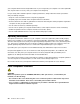
Locating parts on the system board The following illustration shows the locations of the parts on the system board. Figure 4. System board part locations 1 4-pin power connector 2 Microprocessor fan connector 3 Memory slot 1 (DIMM1) 4 Memory slot 2 (DIMM2) 5 Memory slot 3 (DIMM3) 6 Memory slot 4 (DIMM4) 7 Thermal sensor connector 8 Hard disk drive fan connector 9 4-pin power connectors (2) 10 14-pin power connector 11 Power fan connector 12 Parallel connector 13 SATA 3.
Locating internal drives Internal drives are devices that your computer uses to read and store data. You can add drives to your computer to increase storage capacity and enable your computer to read other types of media. Internal drives are installed in bays. When you install or replace an internal drive, note the type and size of the drive that each bay supports and correctly connect the required cables.
Locating the machine type and model label The machine type and model label identifies your computer. When you contact Lenovo for help, the machine type and model information helps support technicians to identify your computer and provide faster service. The machine type and model label is attached on the bottom of your computer as shown. Machine Type: XXXX Model Number: XXX Figure 6. Machine type and model label Features This section introduces the computer features.
• On the Microsoft Windows 8.1 operating system, go to the desktop and move your pointer to the top-right or bottom-right corner of the screen to display the charms. Then click Settings ➙ PC info to view the information. For more information, see “Installing or replacing a memory module” on page 78.
• Memory slots • Optical drive bay • PCI card slot • PCI Express x1 card slots • PCI Express x16 graphics card slot For more information, see “Locating internal drives” on page 7 and “Locating parts on the system board” on page 6.
• Windows Management Instrumentation (WMI) Windows Management Instrumentation is a set of extensions to the Windows Driver Model. It provides an operating system interface through which instrumented components provide information and notification.
Specifications This section lists the physical specifications for your computer. Dimensions Width: 160 mm (6.3 inches) Height: 387.6 mm (15.26 inches) Depth: 421.3 mm (16.59 inches) Weight Maximum configuration as shipped: 7.5 kg (16.5 lb) (without package) Maximum configuration as shipped: 9.0 kg (19.
Note: If you do not find the program you need, open the Lenovo ThinkVantage® Tools program to find the dimmed icon for the program. Then double-click the icon to install the program. To access Lenovo programs through Windows Search, do the following: 1. Click the Start button and then type the program name or the icon name into the search box. 2. Locate the program by the program name or the icon name and then click the program to launch it.
Depending on your computer model, your computer supports some of the following Lenovo programs: • Fingerprint Manager Pro or ThinkVantage Fingerprint Software • Lenovo Bluetooth Lock • Lenovo Companion • Lenovo Reach • Lenovo Settings • Lenovo SHAREit • Lenovo Solution Center • Lenovo Support • Lenovo Tools • Password Manager • PC Cloud Manager • System Update • Wifi Display Receiver An introduction to Lenovo programs This topic provides a brief introduction to some Lenovo programs.
• Lenovo Settings (Windows 8.1) Use the Lenovo Settings program to enhance your computing experience. You can turn your computer into a portable hotspot, configure camera and audio settings, optimize your power plan settings, and create and manage multiple network profiles. • Lenovo SHAREit (Windows 7 and Windows 8.
• View Management Utility (Windows 7) The View Management Utility program enables you to easily organize your open windows. It divides your screen into multiple parts and then resizes and positions open windows into different parts to make the best use of your desktop. The program also is able to work across multiple monitors to improve your productivity. • Wifi Display Receiver (Windows 7 and Windows 8.
Chapter 2. Using your computer This chapter provides information about the following topics: • “Registering your computer” on page 17 • “Using keyboard shortcuts” on page 17 • “Using the fingerprint reader” on page 18 • “Using the wheel mouse” on page 18 • “Setting the computer volume” on page 19 • “Using a disc” on page 20 • “Using the single-touch or multi-touch feature” on page 22 • “Navigating among screens on the Windows 8.
Using the fingerprint reader The integrated fingerprint reader provided on some keyboards enables you to enroll your fingerprint and associate it with your power-on password, hard disk password, and Windows password. As a result, fingerprint authentication can replace passwords and enable simple and secure user access. A fingerprint reader keyboard is available with select computers or can be purchased for computers that support this option.
Advanced configuration and power interface (ACPI) BIOS Being an ACPI BIOS system, the operating system is allowed to control the power management features of the computer and the setting for Advanced Power Management (APM) BIOS mode is ignored. Not all operating systems support ACPI BIOS mode. Automatic Power-on features The Automatic Power-On features within the Power Management menu allow you to enable and disable features that turn on the computer automatically.
4. Click OK to save the new settings. • For Windows 8.1: 1. Open Control Panel, and click Appearance and Personalization. Note: For detailed information on how to open Control Panel on Windows 8.1, see “Accessing Control Panel on the Windows 8.1 operating system” on page 23. 2. In the Taskbar and Navigation section, click Customize icons on the taskbar. 3. Click Turn system icons on or off and change the volume behavior from Off to On. 4. Click OK to save the new settings.
• Do not insert damaged discs into the drive. Warped, scratched, or dirty discs can damage the drive. • Before moving the computer, remove the disc from the drive. Handling and storing a disc When handling and storing a disc, follow these guidelines: • Hold the disc by its edges. Do not touch the surface of the side that is not labeled. • To remove dust or fingerprints, wipe the disc with a clean, soft cloth from the center to the outside. Wiping the disc in a circular direction might cause loss of data.
1. On the Start screen, click the down arrow in the bottom-left corner to go to the Apps screen. Then type Power2Go in the search box in the top-right corner of the screen. 2. Click Power2Go in the search result to open the program. 3. Follow the instructions on the screen. Using the single-touch or multi-touch feature Note: The single-touch and multi-touch features are available only on some models. Depending on your computer model, your computer comes with the single-touch or multi-touch feature.
• Swipe in and out on the left edge of the screen. Representations of all available workspaces are displayed along the left edge of the screen. Tap the Windows screen-control icon at the bottom. • Swipe in from the right edge of the screen to display the charms; then tap Start.
3. Click Control Panel. • From the Start screen 1. Click the down arrow in the bottom-left corner of the screen to go to the Apps screen. 2. Scroll to the right side, and click Control Panel in the Windows System section. Frequently asked questions The following are some of the frequently asked questions and their answers. The answers can help you optimize the use of your computer. For the answers to more frequently asked questions about using your computer, go to: http://www.lenovo.
Chapter 3. You and your computer This chapter provides information about accessibility, comfort, and relocating your computer to other countries or regions. Accessibility and comfort Good ergonomic practice is important to get the most from your personal computer and to avoid discomfort. Arrange your workplace and the equipment you use to suit your individual needs and the kind of work that you perform. In addition, use healthy work habits to maximize your performance and comfort while using your computer.
Glare and lighting Position the monitor to minimize glare and reflections from overhead lights, windows, and other light sources. Reflected light from shiny surfaces can cause annoying reflections on your monitor screen. Place the monitor at right angles to windows and other light sources, when possible. Reduce overhead lighting, if necessary, by turning off lights or using lower wattage bulbs. If you install the monitor near a window, use curtains or blinds to block the sunlight.
On-screen notification On-screen notification helps hearing-impaired people be aware of the status of their computer. On-screen notification replaces sounds with visual cues or text captions to indicate that activity is happening on the computer. As a result, system alerts are noticeable even when they are not heard. For example, when you select one object with your keyboard, the object is highlighted. When you move the pointer to one object with your mouse, the introductory text of the object is displayed.
• For Windows 8.1: Move your pointer to the top-right or bottom-right corner of the screen to display the charms and click Search. Then, type Speech Recognition into the search field. In the list of results, click Speech Recognition. For more information about how to use and configure Speech Recognition, see the Windows Help and Support information system. Customizable text size Depending on your preference, you can change only the text size instead of changing the size of everything on the desktop.
• “Customizable text size” on page 28 • “Magnifier” on page 28 • “Zoom” on page 28 Ease of Access keyboard shortcuts The following table contains keyboard shortcuts that can help make your computer easier to use.
TTY/TDD conversion modem Your computer supports the use of the text telephone (TTY) or the telecommunications device for the deaf (TDD) conversion modem. The modem must be connected between your computer and a TTY/TDD telephone. Then, you can type a message on your computer and send it to the telephone. Documentation in accessible formats Lenovo provides electronic documentation in accessible formats, such as properly tagged PDF files or HyperText Markup Language (HTML) files.
Chapter 4. Security This chapter provides information about how to protect your computer from theft and unauthorized use. Security features The following security features are available on your computer: • Computrace Agent software embedded in firmware The Computrace Agent software is an IT asset management and computer theft recovery solution. The software detects if changes have been made on the computer, such as hardware, software, or the computer call-in location.
Figure 7.
Attaching a Kensington-style cable lock You can use a Kensington-style cable lock to secure your computer to a desk, table, or other non-permanent fixture. The cable lock attaches to the security-lock slot at the rear of your computer. Depending on the type selected, the cable lock can be operated with a key or combination. The cable lock also locks the buttons used to open the computer cover. This is the same type of lock used with many notebook computers.
Attaching a cable lock A cable lock can be used to secure devices, such as the keyboard and the mouse, by locking the device cables to your computer. The cable lock attaches to the cable-lock slots on the rear of your computer. See “Locating connectors on the rear of your computer” on page 3. To install a cable lock, do the following: 1. Insert the clip 1 into the cable-lock slot 4 . 2. Pull the cables you want to lock through the dents in the cable lock. 3.
For more information about BIOS passwords, see “Using BIOS passwords” on page 38.You do not have to set any passwords to use your computer. However, using passwords improves computing security. Windows passwords Depending on your version of the Windows operating system, you can use Windows passwords for a variety of features, including access control and individual user settings. For more information, see the Windows Help and Support information system.
36 ThinkCentre M79 User Guide
Chapter 5. Advanced configuration This chapter provides the following information to help you configure the computer: • “Using the Setup Utility program” on page 37 • “Updating or recovering the BIOS” on page 42 Using the Setup Utility program The Setup Utility program is used to view and change the configuration settings of your computer, regardless of which operating system you are using. However, the operating system settings might override any similar settings in the Setup Utility program.
Using BIOS passwords By using the Setup Utility program, you can set passwords to prevent unauthorized access to your computer and data. You do not have to set any passwords to use your computer. However, using passwords improves computer security. If you decide to set any passwords, read the following topics.
3. Depending on the password type, select Set Power-On Password, Set Administrator Password, or Hard Disk Password. 4. Follow the instructions on the right side of the screen to set, change, or delete a password. Note: A password can be any combination of up to 64 alphabetic and numeric characters. For more information, see “Password considerations” on page 38.
Selecting a startup device If your computer does not start up from a device as expected, do one of the following to select the startup device you want. Selecting a temporary startup device Use this procedure to select a temporary startup device. Note: Not all discs and hard disk drives are bootable. 1. Turn on or restart your computer. 2. When you see the logo screen, repeatedly press and release the F12 key. The Startup Device Menu window is displayed. 3. Select the desired startup device and press Enter.
The wake up on alarm feature enables your computer to wake up at a set time. To enable the wake up on alarm feature, do the following: 1. Start the Setup Utility program. 2. From the Setup Utility program main menu, select Power ➙ Automatic Power On, and press Enter. 3. Select Wake Up on Alarm and press Enter. Then follow the instructions on the screen. 4. Press F10 to save changes and exit the Setup Utility program. Press Enter when prompted to confirm the exit.
1. Start the Setup Utility program. See “Starting the Setup Utility program” on page 37. 2. From the Setup Utility program main menu, select Power. 3. Select Intelligent Cooling Engine (ICE). The Intelligent Cooling Engine (ICE) window is displayed. 4. Select ICE Thermal Alert. The ICE Thermal Alert window is displayed. 5. Select Enabled or Disabled as desired. 6. Press F10 to save changes and exit the Setup Utility program. See “Exiting the Setup Utility program” on page 42.
from other layers of software into electrical signals that the computer hardware can execute. You can use the Setup Utility program to view or change the configuration settings of your computer. See “Using the Setup Utility program” on page 37 for detailed information. The system board of your computer has a module called electrically erasable programmable read-only memory (EEPROM, also referred to as flash memory). It enables you to update the POST, the BIOS, and the Setup Utility program easily.
8. When prompted to change the serial number, it is suggested that you do not make this change by pressing N. However, if you do want to change the serial number, press Y, and then type in the serial number and press Enter. 9. When prompted to change the machine type and model, it is suggested that you do not make this change by pressing N. However, if you do want to change the machine type and model, press Y, and then type in the machine type and model and press Enter. 10.
4. Remove any cables that impede access to the Clear CMOS /Recovery jumper. 5. Move the jumper from the standard position (pin 1 and pin 2) to the maintenance position (pin 2 and pin 3). 6. Reconnect any cables that were disconnected and reinstall the PCI card if removed. 7. Reinstall the computer cover and reconnect the power cords for the computer and monitor to electrical outlets. See “Completing the parts replacement” on page 110. 8.
46 ThinkCentre M79 User Guide
Chapter 6. Preventing problems This chapter provides information that can help you avoid common problems and keep your computer running smoothly. Keeping your computer current In some situations you might find it necessary to have the most current software programs, device drivers, or operating system. This section explains how to get the latest updates for your computer. Getting the latest device drivers for your computer Note: Lenovo makes constant improvements to its Web sites.
Using the System Update program The System Update program (hereinafter referred to as System Update) provides regular access to system and software updates for your computer to keep your system and software up-to-date. System Update gathers information from the Lenovo Help Center about new updates for your computer. Then System Update sorts and displays each update as critical, recommended, or optional to help you understand the importance. You have complete control of which updates to download and install.
1. Apply some isopropyl rubbing alcohol to a soft, dust-free cloth. 2. Wipe each keytop surface with the cloth. Wipe the keys one by one; if you wipe several keys at a time, the cloth may hook onto an adjacent key and possibly damage it. Ensure that no liquid drips onto or between the keys. 3. To remove any crumbs or dust from beneath the keys, you can use a camera blower with a brush or cool air from a hair dryer. Note: Avoid spraying cleaner directly onto the keyboard.
• Clean out your Inbox, Sent Items, and Deleted Items folders in your e-mail application on a regular basis. • Back up critical data regularly on removable media memory, such as discs and USB storage devices, and store the removable media in a safe location. The frequency of making backup copies depends on how critical the data is to you or your business. • Back up your entire hard disk drive on a regular basis. • Keep your computer software, device drivers, and operating system up-to-date.
Chapter 7. Troubleshooting and diagnostics This chapter provides information about diagnosing and troubleshooting computer problems. If your computer problem is not described here, see Chapter 10 “Getting information, help, and service” on page 113 for additional troubleshooting resources. Basic troubleshooting The following table provides some basic instructions to help you troubleshoot your computer problems. Note: If you cannot correct the problem, have the computer serviced.
Symptom Action The operating system does not start. Ensure that the startup sequence includes the device where the operating system resides. Usually, the operating system is on the hard disk drive. For more information, see “Selecting a startup device” on page 40. The computer beeps multiple times before the operating system starts. Ensure that no keys are stuck.
1. Remove the new hardware option or software. If you must remove the computer cover to remove a hardware option, ensure that you review and follow the electrical safety information provided with your computer. For your safety, do not operate the computer with the cover removed. 2. Run the diagnostic program to ensure your computer is operating correctly. 3. Reinstall the new hardware option or software following the instructions provided by the manufacturer.
• If this does not correct the problem, follow the solutions for “A CD or DVD does not work” on page 54. A CD or DVD does not work Solutions: • Ensure that the disc is inserted correctly, with its label up. • Ensure that the disc you are using is clean. To remove dust or fingerprints, wipe the disc clean with a soft cloth from the center to the outside. Wiping a disc in a circular motion might cause loss of data. • Ensure that the disc you are using is not scratched or damaged.
Invalid disc or no disc found message Solutions: • Ensure that a DVD disc is in the drive with the shiny side of the disc facing down. • Ensure that video resolution is set to less than 1152 x 864 pixels. • On computers that have a CD-ROM or CD-RW drive in addition to a DVD-ROM drive, ensure that the DVD disc is in the drive labeled “DVD”. Intermittent problems Some problems occur only occasionally and are difficult to repeat.
• Ensure that the hard disk drive your computer starts from is listed as the first startup device in the Setup Utility program. Refer to “Selecting a startup device” on page 40. Note: In rare cases, the hard disk drive with the operating system might get corrupted or damaged. In such cases, you might need to replace the hard disk drive. Refer to “Replacing the hard disk drive” on page 91. If these actions do not correct the problem, run the diagnostic program Lenovo Solution Center.
• Enroll your fingerprint correctly. • Never scratch the surface of the reader with a hard, pointed object. • Never scrap the surface of the reader with your nail or anything hard. • Use or touch the reader with a clean finger. • Ensure that the surface of your finger is the same with the one when you last enrolled. The wireless keyboard does not work Solutions: • If the transceiver communications LED is not on, reconnect the transceiver and the keyboard.
The image is discolored Solution: The monitor might be affected by interference from nearby equipment. Move fluorescent desk lighting or any equipment that produces magnetic fields further away from the monitor. If the problem persists, do the following: 1. Turn off the monitor. 2. Adjust the placement of the monitor and other devices so that they are at least 305 mm (12 inches) apart. 3. Turn on the monitor. Networking problems This section provides solutions to networking-related problems.
My computer is a Gigabit Ethernet model and I use a speed of 1000 Mbps, but the connection fails or errors occur Solution: Connect the network cable to the Ethernet connector using Category 5 wiring and a 100 BASE-T hub/switch (not 100 BASE-X). My computer is a Gigabit Ethernet model, but it cannot be connected to the network at 1000 Mbps, but at only 100 Mbps Solutions: • Try another cable. • Set the link partner to auto-negotiate. • Set the switch to be 802.3ab-compliant (gigabit over copper).
I have connected an option to my computer, but it does not work Solution: Refer to the documentation that comes with the option to ensure that you have connected the option correctly. Performance and lockup problems This section provides solutions to performance-related problems of your computer. Insufficient free hard disk drive space Solution: Free up hard disk drive space. • Method 1 1. Click Start ➙ Computer on Windows 7 or open File Explorer on Windows 8.1. 2.
3. Right-click your C drive entry and then click Properties. 4. Click Optimize under the Tools tab to start a disk-defragmentation process. Insufficient memory Solution: Install additional memory modules. For instructions on installing memory modules, see “Installing or replacing a memory module” on page 78. To purchase memory modules, go to: http://www.lenovo.com The printer does not work Solutions: • If you are using IEEE-approved printer signal cables, do the following: 1.
• If you are having difficulty with performing a specific task within an application program, refer to the help system for the program. • If you are having difficulty with the Windows operating system or one of its components, refer to the Windows help system. • Check whether the problems are caused by a newly-installed application program. 1. Ensure that the software is compatible with your computer. Refer to the information supplied with the software for more information. 2.
To run the Lenovo Solution Center program, see “Lenovo programs” on page 12. Note: If you cannot isolate and repair the problem yourself after running the program, save and print the log files. You will need the log files when you speak to a Lenovo technical support representative. For additional information, refer to the Lenovo Solution Center help system. Chapter 7.
64 ThinkCentre M79 User Guide
Chapter 8. Recovery information This chapter provides information about the recovery solutions. There are a variety of methods to choose from when considering how to recover from a software- or hardware-related problem. Some methods vary depending on the type of operating system that is installed. You can restore the computer settings using a program or the recovery disc set. For more information about using the recovery disc set, see the documentation that comes with the disc set.
Creating recovery media Note: On the Windows 7 operating system, you can create recovery media using discs or external USB storage devices. To create recovery media on the Windows 7 operating system, click Start ➙ All Programs ➙ Lenovo ThinkVantage Tools ➙ Factory Recovery Disks. Then, follow the instructions on the screen. Using recovery media Attention: When you use recovery media to restore the hard disk drive to the factory-default state, all the files currently on the hard disk drive will be deleted.
• “Performing a recovery operation from the Rescue and Recovery workspace” on page 67 Performing a recovery operation from Windows 7 To perform a recovery operation using the Rescue and Recovery program on the Windows 7 operating system, do the following: 1. From the Windows desktop, click Start ➙ All Programs ➙ Lenovo ThinkVantage Tools ➙ Enhanced Backup and Restore. The Rescue and Recovery program opens. 2. In the Rescue and Recovery main window, click the Launch advanced Rescue and Recovery arrow. 3.
For more information about the features of the Rescue and Recovery workspace, click Help. Creating and using a rescue medium Create rescue media using discs or USB storage devices as early as possible. You can use a rescue medium to recover from failures that prevent you from gaining access to the Windows environment or the Rescue and Recovery workspace on your hard disk drive. Notes: • The recovery operations you can perform using a rescue medium vary depending on the operating system.
Reinstalling preinstalled programs and device drivers Your computer enables you to reinstall preinstalled programs and device drivers. Reinstalling preinstalled programs To reinstall programs preinstalled on your Lenovo computer, do the following: 1. Turn on the computer. 2. Go to C:\SWTOOLS. 3. Open the apps folder and locate the subfolder that is named after the program preinstalled on your computer. 4. Open the subfolder and locate the EXE file. 5.
Note: Reinstall device drivers will change the current configuration of your computer. Reinstall device drivers only when it is necessary to correct a problem with your computer. Solving recovery problems Note: Ensure that your rescue device is set as the first boot device in the startup device sequence in the Setup Utility program. See “Selecting a startup device” on page 40 for detailed information about temporarily or permanently changing the startup device sequence.
2. In the Remove everything and reinstall Windows section, click Get started. Using the advanced startup options Advanced startup options enable you to change the startup settings of your Windows operating system, start the computer from an external device, or restore the Windows operating system from a system image. To use the advanced startup options, do the following: 1. Move the pointer to the top-right or bottom-right corner of the screen to display the charms.
72 ThinkCentre M79 User Guide
Chapter 9. Installing or replacing hardware This chapter provides instructions on how to install or replace hardware for your computer. Handling static-sensitive devices Do not open the static-protective package containing the new part until the defective part has been removed and you are ready to install the new part. Static electricity, although harmless to you, can seriously damage computer components and parts.
CAUTION: Turn off the computer and wait three to five minutes to let the computer cool before removing the computer cover. To remove the computer cover, do the following: 1. Remove any media from the drives and turn off all attached devices and the computer. 2. Disconnect all power cords from electrical outlets. 3. Disconnect the power cord, Input/Output cables, and any other cables that are connected to the computer.
3. Remove the front bezel by releasing the plastic tabs on the left side and pivoting the front bezel outward. Figure 11. Removing the front bezel 4. To reinstall the front bezel, align the plastic tabs on the right side of the front bezel with the corresponding holes in the chassis, then pivot the front bezel inwards until it snaps into position on the left side. Figure 12. Reinstalling the front bezel Chapter 9.
What to do next: • To work with another piece of hardware, go to the appropriate section. • To complete the installation or replacement, go to “Completing the parts replacement” on page 110. Installing or replacing a PCI card Attention: Do not open your computer or attempt any repair before reading and understanding the “Read this first: Important safety information” on page v. This section provides instructions on how to install or replace a PCI card.
4. Depending on whether you are installing or replacing a PCI card, do one of the following: • If you are installing a PCI card, remove the appropriate metal slot cover. • If you are replacing an old PCI card, grasp the old card that is currently installed and gently pull it out of the slot. Notes: – The card fits tightly into the card slot. If necessary, alternate moving each side of the card a small amount until it is removed from the card slot.
Note: If you are installing a PCI Express x16 graphics card, ensure that the memory slot retaining clips are closed before you install the graphics card. 7. Pivot the card latch to the closed position to secure the PCI card. Figure 15. Installing a PCI card 8. Reinstall the screw to secure the card latch in place. What to do next: • To work with another piece of hardware, go to the appropriate section. • To complete the installation or replacement, go to “Completing the parts replacement” on page 110.
UDIMM DIMM 1 DIMM 2 DIMM 3 One UDIMM X Two UDIMMs X, 1 Three UDIMMs X, 1 X, 3 X, 2 Four UDIMMs X, 1 X, 3 X, 2 DIMM 4 X, 2 X, 4 To install or replace a memory module, do the following: 1. Turn off the computer and disconnect all power cords from electrical outlets. 2. Remove the computer cover. See “Removing the computer cover” on page 73. 3. Lay the computer on its side for easier access to the system board. 4. Locate the memory slots. See “Locating parts on the system board” on page 6.
• If you are installing a memory module, open the retaining clips of the memory slot into which you want to install the memory module. Figure 17. Opening the retaining clips 7. Position the new memory module over the memory slot. Ensure that the notch 1 on the memory module aligns correctly with the slot key 2 on the system board. Push the memory module straight down into the slot until the retaining clips close. Figure 18. Installing a memory module 8.
2. Remove the computer cover. See “Removing the computer cover” on page 73. 3. Remove the front bezel. See “Removing and reinstalling the front bezel” on page 74. 4. Depending on whether you are installing or replacing an optical drive, do one of the following: • If you are installing an optical drive, remove the plastic panel in the front bezel for the drive bay you want to use. If there is a metal static shield installed in the drive bay, remove the metal static shield.
6. Slide the new optical drive into the drive bay from the front of the computer until the optical drive snaps into position. Then, install the three screws to secure the new optical drive in place. Figure 21. Installing the optical drive 7. Connect the signal cable and the power cable to the new optical drive. Figure 22. Connecting the optical drive 8. Reinstall the front bezel. See “Removing and reinstalling the front bezel” on page 74.
3. Remove the front bezel. See “Removing and reinstalling the front bezel” on page 74. 4. Record the cable routing of the installed slim card reader and disconnect the cable of the slim card reader from the system board. 5. Remove the screw that secures the slim card reader bracket and then remove the bracket from the chassis. Figure 23. Removing the slim card reader bracket 6. Remove the two screws that secure the slim card reader to the bracket.
Figure 25. Installing the new slim card reader into the bracket 9. Route the cable of the new slim card reader through the corresponding hole for the slim card reader bracket in the front of the chassis. 10. Install the slim card reader bracket into the chassis so that the hole in the bracket is aligned with the corresponding hole in the chassis. Then, Install the screw to secure the slim card reader bracket to the chassis. Figure 26. Installing the slim card reader bracket 11.
Replacing the battery Attention: Do not open your computer or attempt any repair before reading and understanding the “Read this first: Important safety information” on page v. Your computer has a special type of memory that maintains the date, time, and settings for built-in features, such as parallel-connector assignments (configuration). A battery keeps this information active when you turn off the computer.
What to do next: • To work with another piece of hardware, go to the appropriate section. • To complete the installation or replacement, go to “Completing the parts replacement” on page 110. Replacing the heat sink and fan assembly Attention: Do not open your computer or attempt any repair before reading and understanding the “Read this first: Important safety information” on page v. CAUTION: The heat sink and fan assembly might be very hot.
6. Follow the following sequence to remove the four screws that secure the heat sink and fan assembly to the system board: a. Partially remove screw 1 , then fully remove screw 2 , and then fully remove screw 1 . b. Partially remove screw 3 , then fully remove screw 4 , and then fully remove screw 3 . Note: Carefully remove the four screws from the system board to avoid any possible damage to the system board. The four screws cannot be removed from the heat sink and fan assembly. Figure 29.
• To complete the installation or replacement, go to “Completing the parts replacement” on page 110. Replacing the power supply assembly Attention: Do not open your computer or attempt any repair before reading and understanding the “Read this first: Important safety information” on page v. Although there are no moving parts in your computer after the power cord has been disconnected, the following warnings are required for your safety and proper Underwriters Laboratories (UL) certification.
5. Lay the computer on its side and remove the four screws at the rear of the chassis that secure the power supply assembly. Then slide the power supply assembly to the front of the computer and then lift it out of the chassis. Figure 30. Removing the screws for the power supply assembly 6. Ensure that the new power supply assembly is the correct replacement. 7. Install the new power supply assembly into the chassis so that the screw holes in the power supply assembly align with those in the chassis. 8.
1. Remove all media from the drives and turn off all attached devices and the computer. Then, disconnect all power cords from electrical outlets and disconnect all cables that are connected to the computer. 2. Remove the computer cover. See “Removing the computer cover” on page 73. 3. Lay the computer on its side for easier access to the system board. 4. Locate the system board and disconnect all cables connected to the system board. See “Locating parts on the system board” on page 6. 5.
a. Your microprocessor and socket might look different from the one illustrated. b. Note the orientation of the microprocessor in the socket. You can look for the small triangle 1 on one corner of the microprocessor. This is important when installing the new microprocessor on the system board. c. Touch only the edges of the microprocessor. Do not touch the gold contacts on the bottom. d. Do not drop anything onto the microprocessor socket while it is exposed.
5. Remove the four screws that secure the hard disk drive. Then, slide the hard disk drive cage out of the chassis. Figure 33. Removing the hard disk drive 6. Pull on the blue handle to release and remove the hard disk drive from the drive cage. 7. Flex the sides of the blue bracket to remove the hard disk drive from the bracket. 8.
Figure 35. Installing the hard disk drive 11. Connect the signal cable and the power cable to the new hard disk drive. What to do next: • To work with another piece of hardware, go to the appropriate section. • To complete the installation or replacement, go to “Completing the parts replacement” on page 110. Installing the solid-state drive Attention: Do not open your computer or attempt any repair before reading and understanding the “Read this first: Important safety information” on page v.
1. Install the solid-state drive into the storage converter. Then, install the four screws to secure the solid-state drive to the storage converter. Figure 36. Installing the solid-state drive into the storage converter 2. Connect the signal cable and the power cable to the solid-state drive. 3. Install the solid-state drive into the hard disk drive bay. See “Replacing the hard disk drive” on page 91 . What to do next: • To work with another piece of hardware, go to the appropriate section.
5. The rear fan assembly is attached to the chassis by four rubber mounts. Remove the rear fan assembly by breaking or cutting the rubber mounts and gently pulling the rear fan assembly out of the chassis. Note: The new rear fan assembly will have four new rubber mounts attached. Figure 37. Removing the rear fan assembly 6. Install the new rear fan assembly by aligning the new rubber mounts with the corresponding holes in the chassis and push the rubber mounts through the holes. Chapter 9.
7. Pull on the tips of the rubber mounts until the rear fan assembly is secured in place. Figure 38. Installing the rear fan assembly 8. Connect the rear fan assembly cable to the system fan connector on the system board. What to do next: • To work with another piece of hardware, go to the appropriate section. • To complete the installation or replacement, go to “Completing the parts replacement” on page 110.
6. Remove the screw that secures the front audio and USB assembly bracket to the chassis to remove the bracket from the chassis. Figure 39. Removing the screw that secures the front audio and USB assembly to the chassis 7. Remove the two screws that secure the front audio and USB assembly to its bracket and remove the failing front audio and USB assembly from the bracket. 8.
3. Remove the front bezel. See “Removing and reinstalling the front bezel” on page 74. 4. Locate the thermal sensor. See “Locating components” on page 5. 5. Disconnect the thermal sensor cable from the thermal sensor connector on the system board. See “Locating parts on the system board” on page 6. 6. From the inner side of the chassis, pivot the retaining clip 1 inward and then push the clip to the outer side to release it. Then disengage the thermal-sensor plastic holder from the chassis. Figure 40.
8. Insert the new thermal sensor cable into the hole 1 in the chassis. Then align the two tabs on the thermal-sensor plastic holder with the two holes 1 and 2 in the chassis, and push the plastic holder until it snaps into position. Figure 41. Installing the thermal sensor 9. Connect the new thermal sensor cable to the thermal sensor connector on the system board. See “Locating parts on the system board” on page 6. What to do next: • To work with another piece of hardware, go to the appropriate section.
2. Remove the computer cover. See “Removing the computer cover” on page 73. 3. Locate the cover presence switch. See “Locating components” on page 5. 4. Disconnect the cover presence switch cable from the cover presence switch connector on the system board. See “Locating parts on the system board” on page 6. 5. Remove the screw that secures the cover presence switch and remove the cover presence switch from the chassis. Figure 42.
6. Position the new cover presence switch so that the screw hole in the cover presence switch is aligned with the corresponding hole in the chassis. Then install the screw to secure the cover presence switch to the chassis. Figure 43. Installing the new cover presence switch 7. Reconnect the cover presence switch cable to the system board. See “Locating parts on the system board” on page 6. What to do next: • To work with another piece of hardware, go to the appropriate section.
Figure 44. Peeling off the paper that protects the sticker 5. Stick the front antenna to the front panel as shown. Then insert the front antenna cable through the hole in the front panel. Figure 45. Installing the front WiFi antenna 6. Connect the front antenna cable to the Wi-Fi card module. What to do next: • To work with another piece of hardware, go to the appropriate section.
• To complete the installation or replacement, go to “Completing the parts replacement” on page 110. Removing the front Wi-Fi antenna To remove the front Wi-Fi antenna, do the following: 1. Remove all media from the drives and turn off all attached devices and the computer. Then, disconnect all power cords from electrical outlets and disconnect all cables that are connected to the computer. 2. Remove the computer cover. See “Removing the computer cover” on page 73. 3. Remove the front bezel.
Figure 47. Installing the rear Wi-Fi antenna What to do next: • To work with another piece of hardware, go to the appropriate section. • To complete the installation or replacement, go to “Completing the parts replacement” on page 110. Removing the rear Wi-Fi antenna To remove the rear Wi-Fi antenna, do the following: 1. Remove all media from the drives and turn off all attached devices and the computer.
This section provides instructions on how to replace the Wi-Fi units. The Wi-Fi units include a Wi-Fi adapter card, a Wi-Fi card module, and a rear Wi-Fi antenna cable. Replacing the Wi-Fi units involves the following operations: • “Removing the Wi-Fi card module” on page 105 • “Removing the Wi-Fi card module” on page 105 • “Installing the Wi-Fi units” on page 108 Removing the Wi-Fi card module To remove the Wi-Fi card module, do the following: 1.
2. Remove the two screws that secure the Wi-Fi card module to the Wi-Fi adapter card. Figure 50. Removing the screws that secure the Wi-Fi card module 3. Pull the Wi-Fi card module out of the mini PCI Express slot to remove it from the Wi-Fi adapter card. Figure 51. Removing the Wi-Fi card module Removing the Wi-Fi adapter card To remove a Wi-Fi adapter card, do the following: 1. Remove all media from the drives and turn off all attached devices and the computer.
Figure 52. Disconnecting the Bluetooth cable Note: The Bluetooth cable connects the Bluetooth connector on the Wi-Fi adapter card to the front USB connector on the system board to support the Bluetooth function. 4. At the rear of the computer, press the release button 1 to open the PCI card latch 2 . Figure 53. Removing the WiFi adapter card Note: The card fits tightly into the card slot. If necessary, alternate moving each side of the card a small amount until it is removed from the card slot.
What to do next: • To work with another piece of hardware, go to the appropriate section. • To complete the installation or replacement, go to “Completing the parts replacement” on page 110. Installing the Wi-Fi units To install the Wi-Fi units, do the following: 1. Insert the Wi-Fi card module into the mini PCI Express slot, and then install the two screws to secure the Wi-Fi card module to the Wi-Fi adapter card. Figure 54.
2. Connect the front antenna cable and rear antenna cable to the Wi-Fi card module. Figure 55. Installing the Wi-Fi antenna cables 3. Install the Wi-Fi adapter card into the PCI Express x1 slot on the system board. See “Locating parts on the system board” on page 6. 4. If the installed Wi-Fi card module supports the Bluetooth function, use a Bluetooth cable to connect the Bluetooth connector on the Wi-Fi adapter card to the front USB connector on the system board. 5.
2. Connect a new keyboard or mouse to one of the USB connectors on the computer. Depending on where you want to connect the new keyboard or mouse, see “Locating connectors, controls, and indicators on the front of your computer” on page 2 or “Locating connectors on the rear of your computer” on page 3. Figure 57. Connecting the USB keyboard or mouse What to do next: • To work with another piece of hardware, go to the appropriate section.
4. Position the computer cover on the chassis so that the rail guides on the bottom of the computer cover engage the rails on the chassis. Then, push the cover to the front of the computer until it snaps into position. Figure 58. Reinstalling the computer cover 5. Install the screws to secure the computer cover. 6. If there is any locking device available, lock the computer cover. See Chapter 4 “Security” on page 31. 7. Reconnect the external cables and power cords to the computer.
112 ThinkCentre M79 User Guide
Chapter 10. Getting information, help, and service This chapter contains information about help, service, and technical assistance for products manufactured by Lenovo. Information resources You can use the information in this section to access useful resources relating to your computing needs. Lenovo ThinkVantage Tools The Lenovo ThinkVantage Tools program provides easy access to various tools to help you work more easily and securely.
• Access troubleshooting and support information for your computer model and other supported products. • Find the service and support phone numbers for your country or region. • Find a Service Provider located near you. Lenovo Support Web site Technical support information is available on the Lenovo Support Web site at: http://www.lenovo.
• • • • • • Replacement or use of parts not manufactured for or by Lenovo or non-warranted Lenovo parts Identification of software problem sources Configuration of BIOS as part of an installation or upgrade Changes, modifications, or upgrades to device drivers Installation and maintenance of network operating systems (NOS) Installation and maintenance of application programs Refer to the Safety, Warranty, and Setup Guide that comes with your computer for information about your warranty type and duration.
Service availability and service name might vary by country or region. For more information about these services, go to the Lenovo Web site at: http://www.lenovo.
Appendix A. Regulatory information Export classification notice This product is subject to the United States Export Administration Regulations (EAR) and has an Export Classification Control Number (ECCN) of 4A994.b. It can be re-exported except to any of the embargoed countries in the EAR E1 country list. Electronic emissions notices The following information refers to Lenovo personal computer machine types 10CN, 10CQ, 10CR, and 10CS.
This product is in conformity with the protection requirements of EU Council Directive 2004/108/EC on the approximation of the laws of the Member States relating to electromagnetic compatibility. Lenovo cannot accept responsibility for any failure to satisfy the protection requirements resulting from a non-recommended modification of the product, including the installation of option cards from other manufacturers.
Japan VCCI Class B compliance statement Japan compliance statement for products which connect to the power mains with rated current less than or equal to 20 A per phase Lenovo product service information for Taiwan Keyboard and mouse compliance statement for Taiwan Eurasian compliance mark Brazil regulatory notice Ouvir sons com mais de 85 decibéis por longos períodos pode provocar danos ao sistema auditivo.
120 ThinkCentre M79 User Guide
Appendix B. WEEE and recycling information Lenovo encourages owners of information technology (IT) equipment to responsibly recycle their equipment when it is no longer needed. Lenovo offers a variety of programs and services to assist equipment owners in recycling their IT products. For information on recycling Lenovo products, go to: http://www.lenovo.
Disposing of Lenovo computer components Some Lenovo computer products sold in Japan may have components that contain heavy metals or other environmental sensitive substances. To properly dispose of disused components, such as a printed circuit board or drive, use the methods described above for collecting and recycling a disused computer or monitor.
Batteries or packaging for batteries are labeled in accordance with European Directive 2006/66/EC concerning batteries and accumulators and waste batteries and accumulators. The Directive determines the framework for the return and recycling of used batteries and accumulators as applicable throughout the European Union. This label is applied to various batteries to indicate that the battery is not to be thrown away, but rather reclaimed upon end of life per this Directive.
124 ThinkCentre M79 User Guide
Appendix C. Restriction of Hazardous Substances Directive (RoHS) European Union RoHS Lenovo products sold in the European Union, on or after 3 January 2013 meet the requirements of Directive 2011/65/EU on the restriction of the use of certain hazardous substances in electrical and electronic equipment (“RoHS recast” or “RoHS 2”). For more information about Lenovo progress on RoHS, go to: http://www.lenovo.com/social_responsibility/us/en/RoHS_Communication.
Ukraine RoHS India RoHS RoHS compliant as per E-Waste (Management & Handling) Rules, 2011.
Appendix D.
128 ThinkCentre M79 User Guide
Appendix E. ENERGY STAR model information ENERGY STAR® is a joint program of the U.S. Environmental Protection Agency and the U.S. Department of Energy aimed at saving money and protecting the environment through energy efficient products and practices. Lenovo is proud to offer our customers products with an ENERGY STAR compliant designation.
130 ThinkCentre M79 User Guide
Appendix F. Notices Lenovo may not offer the products, services, or features discussed in this document in all countries. Consult your local Lenovo representative for information on the products and services currently available in your area. Any reference to a Lenovo product, program, or service is not intended to state or imply that only that Lenovo product, program, or service may be used.
Trademarks The following terms are trademarks of Lenovo in the United States, other countries, or both: Lenovo The Lenovo logo Rescue and Recovery ThinkCentre ThinkVantage Microsoft, Windows, and Windows Media are trademarks of the Microsoft group of companies. Intel is a trademark of Intel Corporation in the U.S. and/or other countries. Linux is a registered trademark of Linus Torvalds. DisplayPort is a Trademark of the Video Electronics Standards Association.
Index A a rescue medium, creating and using Administrator, password 38 Advance configuration 37 audio features 9 audio line-in connector 4 audio line-out connector 4 68 DisplayPort connector documentation, using drivers, device 111 drives bays 7 specifications 7 4 114 E B backup and recovery operations basic troubleshooting 51 battery, replacing 85 BIOS passwords, using 38 BIOS settings, changing 43 boot-block recovery 44 66 C cable lock, security 33–34 card reader, replacing 82 changing password 38 s
Input/Output (I/O) features installing operating system 43 solid-state drive 93 installing options memory module 78 PCI card 76 internal drives 9 9 slots 76 physical specifications 12 power features 10 power supply assembly, replacing 88 power-on self-test (POST) 42 Power-on, password 38 programs, updating system 42 purchasing additional services 115 K Kensington-style cable lock 33 keyboard connector keyboard, replacing R 4 109 L Lenovo Solution Center 62 Lenovo ThinkVantage Tools 113 locating compone
Setup Utility program, starting 37 Setup Utility, exiting 42 software recovering 65 solid-state drive, installing 93 solving recovery problems 70 starting the Setup Utility program 37 startup device 40 sequence, changing 40 temporary, selecting 40 static-sensitive devices, handling 73 system management 10 programs 42 system board connectors 6 locating parts 6 locations 6 memory module 78 T temporary startup device 40 the BIOS 43 the BIOS, updating 43–44 thermal sensor, replacing 97 trademarks 132 troublesh
136 ThinkCentre M79 User Guide