
User Manual

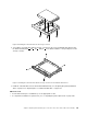
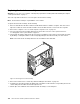
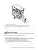
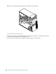
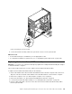
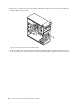
Table Of Contents
- About this manual
- Chapter 1. Safety information
- Chapter 2. General information
- Chapter 3. General checkout
- Chapter 4. Troubleshooting and diagnostics
- Chapter 5. Using the Setup Utility program
- Starting the Setup Utility program
- Viewing and changing settings
- Using passwords
- Enabling or disabling a device
- Selecting a startup device
- Enabling ErP LPS compliance mode
- ICE performance mode
- ICE thermal alert
- Changing the BIOS settings before installing a new operating system
- Exiting the Setup Utility program
- Chapter 6. Symptom-to-FRU Index
- Chapter 7. Locations
- Chapter 8. Replacing FRUs (machine types: 10A0, 10A1, 10A6, 10A7, 10AG, 10AK, 10AL, and 10BE)
- Removing the computer cover
- Removing and reinstalling the front bezel
- Installing or replacing a PCI card
- Installing or replacing a memory module
- Replacing the optical drive
- Installing or replacing the card reader
- Installing or replacing the front USB assembly
- Replacing the battery
- Replacing the power supply assembly
- Replacing the heat sink and fan assembly
- Replacing the microprocessor
- Replacing the system board
- Installing or replacing the mSATA solid-state drive
- Replacing the primary hard disk drive
- Replacing the secondary hard disk drive
- Installing the solid-state drive
- Replacing the front fan assembly
- Replacing the rear fan assembly
- Replacing the front audio and USB assembly
- Replacing the internal speaker
- Replacing the thermal sensor
- Replacing the cover presence switch
- Replacing the Wi-Fi units
- Installing or removing the rear Wi-Fi antenna
- Installing or removing the front Wi-Fi antenna
- Replacing the keyboard or mouse
- Completing the parts replacement
- Chapter 9. Replacing FRUs (machine types: 10A2, 10A3, 10A8, 10A9, 10AH, 10AJ, 10AM, and 10AN)
- Installing external options
- Removing the computer cover
- Removing and reinstalling the front bezel
- Accessing the system board components and drives
- Installing or replacing a PCI card
- Installing or replacing a memory module
- Replacing the optical drive
- Installing or replacing the card reader assembly
- Installing or replacing the front USB assembly
- Replacing the battery
- Installing or replacing the mSATA solid-state drive
- Replacing the power supply assembly
- Replacing the power switch unit
- Replacing the heat sink and fan assembly
- Replacing the microprocessor
- Replacing the system board
- Replacing the cover presence switch
- Replacing the primary hard disk drive
- Installing or replacing the secondary hard disk drive
- Installing the solid-state drive
- Replacing the front fan assembly
- Replacing the front audio and USB assembly
- Replacing the internal speaker
- Replacing the thermal sensor
- Replacing the Wi-Fi units
- Installing or removing the rear Wi-Fi antenna
- Installing or removing the front Wi-Fi antenna
- Replacing the keyboard or mouse
- Completing the parts replacement
- Chapter 10. Replacing FRUs (machine types: 10A4, 10A5, 10AA, 10AB, 10DF, 10DG, 10DH, 10DJ, 10E8, 10E9, 10EA, and 10EB)
- Removing the computer cover
- Installing external options
- Installing or removing the ac power adapter
- Installing or removing the vertical stand
- Installing or removing the VESA mount bracket
- Installing or removing the ac power adapter bracket
- Replacing the optical drive
- Installing or removing the hard disk drive assembly
- Replacing the secondary hard disk drive
- Installing or removing the I/O box
- Installing or replacing a memory module
- Replacing the battery
- Replacing the power switch board
- Replacing the Wi-Fi card module
- Installing or removing the front Wi-Fi antenna
- Installing or removing the rear Wi-Fi antenna
- Replacing the internal speaker
- Replacing the cover presence switch
- Replacing the system fan
- Replacing the thermal module
- Replacing the microprocessor
- Replacing the system board
- Replacing the keyboard or mouse
- Completing the parts replacement
- Chapter 11. Additional service information
- Appendix A. Notices
- Index

Figure 70. Installing the solid-state drive into the storage converter
2. To install the solid-state drive with the storage converter into the 3.5-inch hard disk drive bracket, flex
the bracket and align pin
1 , pin 2 , pin 3 , and pin 4 on the bracket with the corresponding holes in the
storage converter.
Figure 71. Installing the solid-state drive with the storage converter into the hard disk drive bracket
3. Install the solid-state drive into the desired hard disk drive bay. See “Replacing the primary hard disk
drive” on page 122 or “Replacing the secondary hard disk drive” on page 124.
What to do next:
• To work with another piece of hardware, go to the appropriate section.
• To complete the installation or replacement, go to “Completing the parts replacement” on page 150.
Chapter 8. Replacing FRUs (machine types: 10A0, 10A1, 10A6, 10A7, 10AG, 10AK, 10AL, and 10BE) 127