
Computer Hardware User Manual

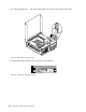


6.Removethetwoscrewsthatsecuretheheatsinkfanduct.Thenremovetheheatsinkfanductfrom
thefailingheatsinkandfanassembly.
Figure78.Removingtheheatsinkfanduct
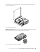
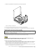
7.Placethenewheatsinkandfanassemblyonthesystemboardsothatthefourscrewsarealigned
withthecorrespondingholesinthesystemboard.Makesurethatyouproperlyplacethenewheat
sinkandfanassemblysothatyoucaneasilyconnectthenewheatsinkandfanassemblycabletothe
microprocessorfanconnectoronthesystemboard.
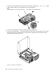
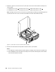
8.Followthissequencetoinstallthefourscrewstosecurethenewheatsinkandfanassembly,asshown
inFigure77“Screwsthatsecuretheheatsinkandfanassembly”onpage140:
a.Partiallytightenscrew1,thenfullytightenscrew2,andthenfullytightenscrew1.
b.Partiallytightenscrew3,thenfullytightenscrew4,andthenfullytightenscrew3.
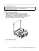
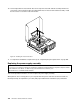
9.Connectthenewheatsinkandfanassemblycabletothemicroprocessorfanconnectoronthesystem
board.See“Locatingpartsonthesystemboard”onpage77
.
Chapter9.ReplacingFRUs(MachineTypes:4466,4471,4474,4477,4480,4485,4496,4498,4503,4512,4514,
4518,4554,7005,7023,7033,7035,7072,7079,and7177.)141