
Computer Hardware User Manual
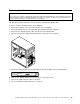
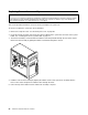
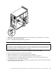
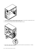
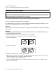


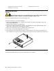
Table Of Contents
- Chapter 1. About this manual
- Chapter 2. Safety information
- Chapter 3. General information
- Chapter 4. General Checkout
- Chapter 5. Diagnostics
- Chapter 6. Using the Setup Utility
- Chapter 7. Symptom-to-FRU Index
- Chapter 8. Replacing FRUs (Types 7061, 7090, 9353, 9421, 9485, 9
- Locating controls and connectors on the front of your computer
- Rear connectors
- Removing the cover
- Locations
- Locating parts on the system board
- Removing and replacing the front bezel
- Replacing the power supply
- Replacing the system board
- Replacing the microprocessor
- Replacing a memory module
- Replacing a PCI adapter card
- Replacing the hard disk drive
- Replacing an optical drive
- Replacing the diskette drive
- Replacing the rear fan assembly
- Replacing the front fan assembly
- Replacing the front audio/USB assembly
- Replacing the power switch/LED assembly
- Replacing the CMOS battery
- Completing the FRU replacement
- Chapter 9. Replacing FRUs (Types 7057, 7062, 7092, 9342, 9344, 9
- Rear connectors
- Removing the cover
- Locations
- Locating parts on the system board
- Accessing system board components and drives
- Replacing a memory module
- Replacing the CMOS battery
- Replacing the power supply
- Replacing the system board
- Replacing the microprocessor
- Replacing the hard disk drive
- Replacing an optical drive
- Replacing the diskette drive
- Replacing the power switch/LED assembly
- Replacing the front panel card
- Replacing the system fan assembly
- Replacing a PCI adapter card
- Completing the FRU replacement
- Chapter 10. FRU lists
- Machine Type 3656
- Machine Type 3658
- Machine Type 7057
- Machine Type 7061
- Machine Type 7062
- Machine Type 7090
- Machine Type 7092
- Machine Type 9342
- Machine Type 9344
- Machine Type 9353
- Machine Type 9354
- Machine Type 9421
- Machine Type 9426
- Machine Type 9485
- Machine Type 9486
- Machine Type 9623
- Machine Type 9624
- Machine Type 9625
- Machine Type 9705
- Machine Type 9707
- Machine Type 9795
- Machine Type 9804
- Machine Type 9935
- Machine Type 9945
- Machine Type 9946
- Machine Type 9953
- Chapter 11. Additional Service Information
- Appendix A. Notices

8.Replacethefrontbezel.
9.Goto"CompletingtheFRUreplacement"onpage113.
Replacingthefrontaudio/USBassembly
Attention
Donotopenyourcomputerorattemptanyrepairbeforereadingandunderstandingthe"Importantsafetyinformation"
intheThinkCentreSafetyandWarrantyGuidethatcamewithyourcomputer.ToobtainacopyoftheThinkCentre
SafetyandWarrantyGuide,goto:http://www.lenovo.com/support
Thissectionprovidesinformationonhowtoremoveandreplacethefrontaudio/USBassembly.
Toremoveorreplacethefrontaudio/USBassembly,dothefollowing:
1.Removethecomputercover.See"Removingthecover"onpage68.
2.Removethefrontbezel.See"Removingandreplacingthefrontbezel"onpage71
3.Disconnectthefrontaudio/USBassemblycablefromthesystemboard.See"Locatingpartsonthe
systemboard"onpage71.
4.Notethefrontaudio/USBassemblycableroutingandremovethescrewthatsecurestheassemblyto
thechassis.
5.Removethefrontaudio/USBassembly.
6.Routethecableforthenewfrontaudio/USBassemblythroughtheholeinthechassisandtothesystem
board.
7.Installthefrontaudio/USBassemblyintothechassisandsecureitwiththescrew.
8.Connectthefrontaudio/USBassemblycabletothesystemboard.
9.Reinstallthefrontbezel.
10.Goto"CompletingtheFRUreplacement"onpage91.
Replacingthepowerswitch/LEDassembly
Attention
Donotopenyourcomputerorattemptanyrepairbeforereadingandunderstandingthe"Importantsafetyinformation"
intheThinkCentreSafetyandWarrantyGuidethatcamewithyourcomputer.ToobtainacopyoftheThinkCentre
SafetyandWarrantyGuide,goto:http://www.lenovo.com/support
Thissectionprovidesinformationonhowtoremoveandreplacethepowerswitch/LEDassembly.
Toremoveorreplacethepowerswitch/LEDassembly,dothefollowing:
1.Removethecomputercover.See"Removingthecover"onpage68.
2.Removethefrontbezel.See"Removingandreplacingthefrontbezel"onpage71
3.Disconnectthepowerswitch/LEDassemblycablefromthesystemboard.See"Locatingpartsonthe
systemboard"onpage71.
4.Notethepowerswitch/LEDassemblycableroutingandthepositionofthetwoLEDs.
5.RemovetheswitchandtheLEDsfromthebezel.
6.Routethecableforthenewpowerswitch/LEDassemblythroughtheholeinthechassisandtothe
systemboard.
7.Installthenewpowerswitch/LEDassemblyintothebezel.MakesurethattheLEDsareinthecorrect
position.
8.Connectthepowerswitch/LEDcabletothesystemboard.
Chapter8ReplacingFRUs(Types7061,7090,9353,9421,9485,9623,9625,9705,9786,9795,9935,9946,9953)89