
Personal Computer Hardware Maintenance Manual
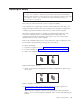


Table Of Contents
- Contents
- Chapter 1. About this manual
- Chapter 2. Safety information
- Chapter 3. General information
- Chapter 4. General checkout
- Chapter 5. Diagnostics
- Chapter 6. Using the Setup Utility
- Chapter 7. Symptom-to-FRU index
- Chapter 8. Replacing FRUs
- Locations
- Opening the computer cover
- Replacing the battery
- Replacing a memory module
- Replacing the adapter card
- Replacing the front audio and USB assembly
- Replacing the heat sink
- Replacing the microprocessor
- Replacing the system board
- Replacing the system fan
- Replacing the hard disk drive
- Replacing the optical drive
- Replacing the internal speaker
- Completing the FRU replacement
- Chapter 9. FRU lists
- Chapter 10. Additional service information
- Appendix. Notices
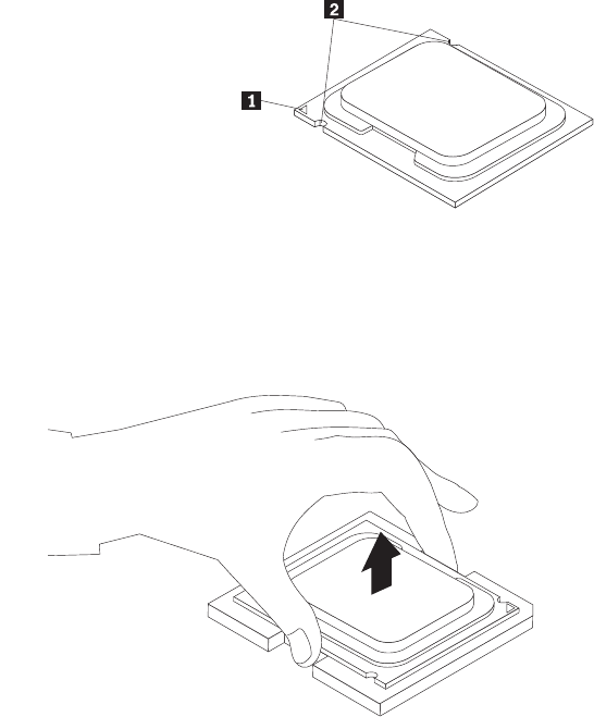
6. Lift the microprocessor straight up and out of the socket.
Notes:
a. Your microprocessor and socket might look different from the one
illustrated.
b. Note the orientation of the microprocessor in the socket. You can either
look for the small triangle 1 on one corner of the microprocessor or note
the orientation of the notches 2 on the microprocessor. This is important
when installing the new microprocessor on the system board.
c. Touch only the sides of the microprocessor. Do not touch the gold contacts
on the bottom.
d. Do not drop anything onto the microprocessor socket while it is exposed.
The socket pins must be kept as clean as possible.
7. Make sure that the small handle is in the raised position and the
microprocessor retainer is fully open.
Figure 16. Removing the microprocessor
94 Hardware Maintenance Manual