
Personal Computer Hardware Maintenance Manual
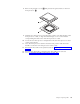


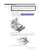
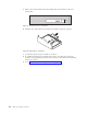
Table Of Contents
- Contents
- Chapter 1. About this manual
- Chapter 2. Safety information
- Chapter 3. General information
- Chapter 4. General checkout
- Chapter 5. Diagnostics
- Chapter 6. Using the Setup Utility
- Chapter 7. Symptom-to-FRU index
- Chapter 8. Replacing FRUs
- Locations
- Opening the computer cover
- Replacing the battery
- Replacing a memory module
- Replacing the adapter card
- Replacing the front audio and USB assembly
- Replacing the heat sink
- Replacing the microprocessor
- Replacing the system board
- Replacing the system fan
- Replacing the hard disk drive
- Replacing the optical drive
- Replacing the internal speaker
- Completing the FRU replacement
- Chapter 9. FRU lists
- Chapter 10. Additional service information
- Appendix. Notices
7. Remove the adapter card from the failing system board. See “Replacing the
adapter card” on page 88.
8. Remove the battery from the failing system board. See “Replacing the battery”
on page 85.
9. Remove the microprocessor from the failing system board. See “Replacing the
microprocessor” on page 93.
10. Remove the screws that secure the failing system board to the protective
cover.
11. Lift the failing system board off the cover.
12. Position the new system board so that the screw holes are aligned with the
mounting studs on the cover.
13. Install the screws to secure the new system board to the protective cover.
14. Install the memory modules, adapter card, battery, and microprocessor that
you removed from the failing system board to the new system board.
15. Slide the new system board to the rear of the chassis and then pivot it inward
until it is locked into position.
16. Connect all the cables to the new system board. See“Locating parts on the
system board” on page 83.
17. Install the heat sink to the new system board. See “Replacing the heat sink”
on page 91.
18. Go to “Completing the FRU replacement” on page 106.
The
failing system board must be returned with a microprocessor socket cover to
protect the pins during shipping and handling.
To install the microprocessor socket cover:
1. Remove the microprocessor from the microprocessor socket. See “Replacing the
microprocessor” on page 93.
2. Close the microprocessor retainer and lock it into position with the small
handle.
Chapter 8. Replacing FRUs 97