
Personal Computer Hardware Maintenance Manual


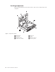


Table Of Contents
- Contents
- Chapter 1. About this manual
- Chapter 2. Safety information
- Chapter 3. General information
- Chapter 4. General checkout
- Chapter 5. Diagnostics
- Chapter 6. Using the Setup Utility
- Chapter 7. Symptom-to-FRU index
- Chapter 8. Replacing FRUs
- Locations
- Opening the computer cover
- Replacing the battery
- Replacing a memory module
- Replacing the adapter card
- Replacing the front audio and USB assembly
- Replacing the heat sink
- Replacing the microprocessor
- Replacing the system board
- Replacing the system fan
- Replacing the hard disk drive
- Replacing the optical drive
- Replacing the internal speaker
- Completing the FRU replacement
- Chapter 9. FRU lists
- Chapter 10. Additional service information
- Appendix. Notices

Locating parts on the system board
The following illustration shows the locations of parts on the system board.
1 Microprocessor 9 PCI slot
2 Clear CMOS/Recovery jumper 10 Front USB connector 2
3 Thermal sensor connector 11 Intrusion switch connector/Cover
presence switch connector
4 Battery 12 Front I/O and LED/Switch header
5 Memory slots (2) 13 eSATA connector
6 Internal speaker connector 14 Internal power distribution connector
7 Serial (COM) connector 15 System fan connector
8 SATA connectors (2)
Figure 4. System board parts locations
Chapter 8. Replacing FRUs 83