
Personal Computer Hardware Maintenance Manual
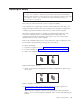


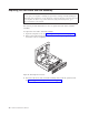
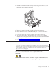
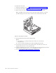
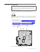

Table Of Contents
- Contents
- Chapter 1. About this manual
- Chapter 2. Safety information
- Chapter 3. General information
- Chapter 4. General checkout
- Chapter 5. Diagnostics
- Chapter 6. Using the Setup Utility
- Chapter 7. Symptom-to-FRU index
- Chapter 8. Replacing FRUs
- Locations
- Opening the computer cover
- Replacing the battery
- Replacing a memory module
- Replacing the adapter card
- Replacing the front audio and USB assembly
- Replacing the heat sink
- Replacing the microprocessor
- Replacing the system board
- Replacing the system fan
- Replacing the hard disk drive
- Replacing the optical drive
- Replacing the internal speaker
- Completing the FRU replacement
- Chapter 9. FRU lists
- Chapter 10. Additional service information
- Appendix. Notices

6. Turn on the computer and all attached devices.
7. Use the Setup Utility program to set the date, time, and any passwords. See
Chapter 6, “Using the Setup Utility,” on page 49.
Replacing a memory module
Attention
Do not open your computer or attempt any repair before reading and understanding the
“Important safety information” in the ThinkCentre Safety and Warranty Guide that came with
your computer. To obtain a copy of the ThinkCentre Safety and Warranty Guide, go to:
http://www.lenovo.com/support
This section provides instructions on how to replace a memory module.
Your computer has two slots for installing or replacing SODIMMs (small outline
dual inline memory modules) that provide up to a maximum of 4 GB of system
memory.
When installing or replacing a memory module, use the following guidelines:
v Use 1.8 V, 200-pin DDR3 SDRAM (double data rate 3 synchronous dynamic
random access memory).
v Use 1 GB or 2 GB memory modules in any combination up to a maximum of 4
GB.
To replace a memory module:
1. Open the computer cover. See “Opening the computer cover” on page 84.
2. Locate the memory slot. See “Locating parts on the system board” on page 83.
3. Remove the memory module being replaced by opening the retaining clips as
shown.
Figure 8. Removing the memory module
86 Hardware Maintenance Manual