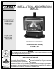
INSTALLATION AND OPERATION MANUAL FREESTANDING VENTED GAS FIREPLACE HEATER RETAIN THESE INSTRUCTIONS FOR FUTURE REFERENCE Shown with optional gold door and brickaded interior MODELS L30 BF-2 (B-Vent) P/N 775030M, IR, 06/01 WARNING If the information in this manual is not followed exactly, a fire or explosion may result causing property damage, person injury or loss of life. Do not store or use gasoline or other flammable vapors and liquids in the vicinity of this or any other appliance.
IMPORTANT WARNINGS / CAUTIONS CAUTION: Read this manual thoroughly before starting installation. For your safety, follow the installation, operation and maintenance instructions exactly without deviation. Failure to follow these instructions may result in a possible fire hazard and may void the warranty. If this appliance is not properly installed, a house fire may result. Contact local building or fire officials about restrictions and installation inspection in your area. 1.
TABLE OF CONTENTS Important Warnings ................................................ 2 CONGRATULATIONS ON THE PURCHASE OF YOUR NEW GAS APPLIANCE MANUFACTURED BY LENNOX HEARTH PRODUCTS. Testing / Listing, Using this Manual ........................ 3 Planning Your Installation .....................................
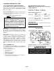
PLANNING YOUR INSTALLATION LOCAL AND NATIONAL CODE REQUIREMENTS The installation of these appliances must conform with local codes or, in the absence of local codes, with the National Fuel Gas Code, (for USA) NFPA 54 / ANSI Z223.1-latest edition. Air Circulation Blower: The blower electrical power cord must be electrically grounded per local codes or per electrical codes: In USA, NEC, ANSI / NFPA 70-1987. In Canada, CSA C22.
PLANNING YOUR INSTALLATION QUESTIONS TO ASK THE LOCAL BUILDING OFFICIAL 5. In some states or municipalities, a licensed gas fitter or plumber may be required to install this appliance. Check with your local building official for requirements in your area (i.e. Is a license required for installation of gas supply line)? Correct installation is critical and imperative for reducing fire hazards and perilous conditions that can arise when gas appliances function improperly.
PLANNING YOUR INSTALLATION Rear Wall or Alcove CLEARANCES TO COMBUSTIBLE MATERIALS These appliances can be installed in most residential room configurations, parallel to a rear or adjacent wall, or in an alcove that allows for the minimum clearances to combustible surfaces. Your local building inspector should review your plans prior to installation. When installing this appliance, provide adequate clearances around air openings and adequate clearances for purposes of servicing and proper operation.
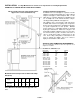
INSTALLATION See Pipe Manufacturers clearances for Pipe Clearances Venting Requirements EXAMPLES OF VENTING INSTALLATION APPLICATIONS Model: L30 BF-2 (B-Vent) Venting Requirements Approved for vertical termination only. Venting Configuration Requirements: A minimum of 5 feet vertical pipe is required to vent the appliance. Lengthy horizontal pipe runs require sufficient length of vertical pipe to deliver adequate draft. Use the table above as a guide in planning your installation.
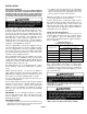
INSTALLATION GAS SUPPLY HOOKUP If using pipe other than black iron pipe see NFPA 54-National Fire Protection Association / ANSI Z223.1-American National Standards Institute; and local code for specific requirements for the type of pipe used. Alternative gas piping systems such as CSST may be used subject to local code and proper sizing. This appliance is equipped with a flexible gas line and fitting for a gas supply line connection.
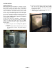
INSTALLATION DOOR OPERATION After setup of the logs and embers is complete, the glass door must be closed. The glass door is mounted on hinges at the left side of the firebox and is secured in the closed position by two draw latches mounted on the right side of the firebox. The latch tension is preset at the factory. Over time, adjustment of the latch tension may be necessary to maintain a tight door seal. This adjustment can be made by spinning the latching rod in the rod guide.
INSTALLATION GAS APPLIANCE FINAL ASSEMBLY After the appliance has been properly installed and all gas connections have been made and tested, you can now install the log set. See Door Assembly on page 11 for door removal instructions. 4. Install the center top twig as shown in the following illustration.
INSTALLATION INSTALLATION CHECK LIST Read and understand these instructions before using appliance. Go through this installation checklist: G Ensure that the log set is properly installed. Use caution when handling the logs. See page 10. G Reinstall the door frame assembly. See Door Operation on page 9. 2. Adjust gap as shown in following picture. WARNING: Do not operate appliance with the glass front removed, cracked or broken. Replacement of the glass should be done by a qualified technician. 3.
CARE AND OPERATION FOR YOUR SAFETY READ BEFORE LIGHTING WARNING: If you do not follow these instructions exactly, a fire or explosion may result causing property damage, personal injury or loss of life. A. This appliance has a pilot which must be lit. When lighting the pilot, follow these instructions exactly. B. BEFORE LIGHTING smell all around the appliance area for gas. Be sure to smell next to the floor because some gas is heavier than air and will settle on the floor.
CARE AND OPERATION “BREAK-IN” PERIOD The finish on this appliance is a high temperature paint that requires time and temperature to completely cure. The curing process will take 2 or 3 burns (heat up and cool down periods). We recommend that you ventilate the house during the initial burns. The paint emits nontoxic odors during this process. KEEP YOUR HOUSE WELL VENTILATED DURING THE CURING PROCESS TO PREVENT ACTIVATION OF YOUR HOME SMOKE DETECTOR. Do not turn on a blower during the break-in period.
PROPANE CONVERSION PROPANE CONVERSION PROCEDURE (Only required if Propane gas is used) This appliance is designed to operate on natural gas, or propane (LP). It is factory set for use with natural gas and requires field conversion for use with propane. The use of other fuels or combination of fuels will degrade the performance of this system and may be dangerous.
PROPANE CONVERSION 7. High / Low Pressure Regulator Installation Procedure: a.Remove regulator cap and conversion screw (see following illustration). b.Install the new conversion screw (Red = Propane LP gas, Blue = Natural Gas). Ensure that the conversion screw is finger tight. Install the new regulator cap. c. Affix conversion label on gas control valve body where it can easily be seen. 10. Purge air from the gas line (see #9 above), then connect propane gas line to the appliance.
MAINTENANCE Always Turn Off Gas Control Valve Before Cleaning. Annual Maintenance Should Only Be Performed By A Qualified Service Technician: LOG SET Removing & Cleaning Logs - Carefully remove the logs (removing top logs, then lifting front log out, then rear log). Use care when handling the fiber logs, as they become quite fragile after curing. Use a small soft-bristled brush (e.g., a nylon paint brush) to remove soot, dust or debris that may have accumulated on the burner or log set.
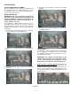
MAINTENANCE Always Turn Off Gas Control Valve Before Cleaning. Annual Maintenance Should Only Be Performed By A Qualified Service Technician: PERIODIC CHECK OF PILOT AND BURNER FLAMES Check the operation of the pilot and cycle the burner. Visually check the flame of the burner making sure the flames are steady; not lifting or floating. The flame color should be blue at the burner with yellow body and tops. BURNER FLAME APPEARANCE A periodic visual check of the pilot and burner flames should be performed.
WIRING DIAGRAMS GAS CONTROL AND SAFETY SYSTEM WIRING DIAGRAM CAUTION: Label all wiring prior to disconnection when servicing controls. Wiring errors can cause improper and dangerous operation. Verify proper operation after servicing. The gas control wiring diagram shown here should be used by service technicians for guidance when troubleshooting problems with the pilot safety (millivolt) system or burner remote control system or when locating system components for repair / replacement.
TROUBLESHOOTING Qualified Technicians Only PROBLEM 1) Pilot will not light, and Piezo Igniter does not produce a heavy blue spark. 2) Pilot will not light, but Piezo Igniter produces a heavy blue spark. 3) Pilot will not stay lit. 4) Pilot flame stays lit, but main burner will not light. 5) Main burner stays lit for up to 10 minutes and then shuts off, pilot flame remains lit. 6) Smell of gas 7) A thin coating of black soot forms on the window. NOTE: See page 16, Cleaning Glass. CAUSE(S) a.
REPLACEMENT PARTS Item # 1 2 3 4 5 6 7 8 Model L30-2 BF Description Trim, Decorative Window Frame, Charcoal Burner Assembly Blower, Air Circulating Power Cord (blower) Rheostat w / Knob (speed control for blower) On / Off Switch, Burner Spill Switch Catalog # 52L04 17M63 17M61 52L19 52L17 52L03 52L13 52L18 Item # 9 10 11 11 11 11 12 13 PAGE 20 Description Thermal Fan Switch Control Valve NG (with LP Conv.
OPTIONAL ACCESSORIES Item # 1 2 3 4 5 6 Description Door Kit, L30 BF-2, Gold Brickaded Interior Kit, L30 Deluxe Remote Control (Thermostatically controlled) Remote Control (Standard On / Off) Wall Thermostat Kit Touch-up Spray Paint Kit, Charcoal (3) Deluxe Remote Features PAGE 21 Catalog # 14M09 14M06 98K99 26N04 89L36 19L92 Model DK3B-G BRK-L30 RC-STAT RC WTK TSPK-C
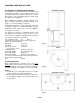
SPECIFICATIONS: Model L30 BF-2 Top View Approx. Sq. Ft. Heating Capacity ∼1500 sq. ft. Flue Size 4” - Top Vent Height Overall Height to Flue Outlet 29” Width 29 7/8” Depth 16 1/8” Fuel Natural Gas (standard) (or) LP Gas (convertible). Gas inlet 3/8” NPT-Male / Flex Line (or) remove flex, 3/8” NPT–Female Flare. 30 3/8” Performance Features Variable Flame Control. High Efficiency Heat Exchanger. Natural Convection & Radiant Heat. Standing Pilot / Operates During Power Outages.
SAFETY / LISTING LABEL: Model L30 BF-2 PAGE 23
OWNERSHIP RECORDS Dealer’s Name: Dealer’s Address: City: State: Zip Code: Serial Number: Date of Purchase: Date Installed: Notes: SERVICE AND MAINTENANCE LOG Service Service Service Date Technician Description PAGE 24
1110 West Taft Avenue Orange, CA 92865