MODEL HT-391 Home Theater System Turns Your DVD Player Into a 5.1 Channel Home Theater Surround Sound System The Perfect Sound System for Your DVD Player • • Just add your TV & DVD player; everything else is in the box. Incredible surround sound, perfect for DVD viewing & enhanced TV game experience.
SAFETY INSTRUCTIONS WARNING TO PREVENT FIRE OR SHOCK HAZARD, DO NOT USE THE PLUG WITH AN EXTENSION CORD, RECEPTACLE OR OTHER OUTLET UNLESS THE BLADES CAN BE FULLY INSERTED TO PREVENT BLADE EXPOSURE. TO PREVENT FIRE OR SHOCK HAZARD, DO NOT EXPOSE THIS APPLIANCE TO RAIN OR MOISTURE. RISK OF EL ECTRIC SHOCK DO NOT OPEN WARNING: TO REDUCE THE RISK OF ELECTRIC SHOCK, DO NOT REMOVE COVER (OR BACK). NO USER SERVICEABLE PA RT S IN SI DE . R EF ER SE RV IC ING T O QUA LI FI ED SERVICE PERSONNEL.
INTRODUCTION Thank you for purchasing this 5.1 Channel Home Theater Surround Sound System. This deluxe audio theater system turns your home into a virtual theater. In addition to the incredible surround sound of a 5.1 channel audio source, such as your current DVD player, this system also superbly enhances your other audio sources, such as a CD player, computer, VCR, or a cassette deck. The only thing you need to add is your own TV or other devices.
TABLE OF CONTENTS • Getting Started Safety Instructions-------------------------------------------------------------------------------------------------------------------------------------1 Introduction----------------------------------------------------------------------------------------------------------------------------------------------- 2 Location of Controls----------------------------------------------------------------------------------------------------------------------------------- 4,5 Remote C
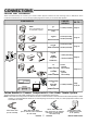
LOCATION OF CONTROLS FRONT OF MAIN SET (SUBWOOFER) 6 7 1 8 9 10 11 12 13 2 14 5 3 4 BACK OF MAIN SET (SUBWOOFER) 15 16 17 19 20 18 20 21 21 22 22 23 23 24 24 26 25 27 1. ON / STANDBY button - Press to switch the set to on or to standby mode. 2. INPUT SOURCE button - Press several times to select the sound input source you want: DVD, AUX or GAME. 3. SPEAKER CHANNELS button - Press to select 2 channel or 5.1 channel listening mode. 4.
LOCATION OF CONTROLS REMOTE CONTROL 1 2 5 3 6 4 7 8 9 1. IR DIODE - Sends the signal to the set. Do not block or cover this. 2. ON/STANDBY button - Switches the player from STANDBY to ON or ON to STANDBY (if the main POWER of the set is ON). 3. SOURCE button - Press to select the sound input source you want: DVD, AUX or GAME. 4. RESET button - Press to adjust all speakers’ output to the factory’s default settings. 5. MUTE button - Instantly turns off the sound. Press again to restore the sound. 6.
REMOTE CONTROL OPERATION Battery Installation Remote Control Operating Range Remove the BATTERY COMPARTMENT DOOR of the REMOTE CONTROL and insert 2 size “AAA” alkaline batteries (included) according to the + and markings inside the BATTERY COMPARTMENT of the REMOTE CONTROL unit. Point the REMOTE CONTROL unit within 20 feet from the remote control sensor and facing the front of the HOME THEATER SYSTEM. Gently push here and slide to open the BATTERY DOOR. Slide door down.
CONNECTIONS Choose Your Connection There are several ways to connect your Home Theater System. Please use the following chart to determine which connection is the best for you. Turn to the appropriate page and connect your Home Theater System. CABLES NEEDED COMPONENTS NOTE: This only applies if your TV has audio out jacks.
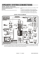
SPEAKER SYSTEM CONNECTIONS Speaker System Connections Connect the supplied speaker system by matching the colors of the terminals to those of the cords. The speaker wires and connectors are color-coded for easier set up. • Connect the Front Left speaker to the Front Left terminals. • Connect the Front Right speaker to the Front Right terminals. • Connect the Center speaker to the Center speaker terminals. • Connect the Rear Left speaker to the Rear Left terminals.
SPEAKER SYSTEM CONNECTIONS Tips for connecting the speaker wires To avoid short-circuiting the speakers Unwind and stretch out the speaker wires attached with each speakers, then push and hold down the speaker terminal tab on the back of the main set to insert each wire. Make sure the wire is fully inserted, but the insulation is not covering the inserted part of the speaker wires.
SPEAKER POSITIONING INFORMATION Your system is supplied with 5 compact sized satellite speakers and one large subwoofer (main set). The satellite speakers and the center speaker reproduce only the mid range and higher frequencies. All of the low frequency (bass) sounds are produced by the subwoofer. Proper positioning and placement of the speakers is important in order to provide the best surround sound experience.
SPEAKER POSITIONING INFORMATION • The left front, right front, and center speakers should be placed at roughly the same height. The center speaker reproduces most of the dialog spoken by the actors on the TV screen, therefore it should be placed either directly above or below the center of the TV set. Once you position the center speaker, try to position the left front and right front speakers at the same height. It is not recommended to place any of the satellite speakers on the floor.
TV CONNECTIONS (If you don’t have a DVD player yet) Home Theater System + TV (if your TV has Audio Output jacks) NOTE: On some TVs, these jacks are in the front, or your TV may not have these jacks. NOTE: If your TV does not have audio output jacks, your TV’s sound cannot be heard through the surround sound system. But, you can still use it for your DVD player etc.
TV + DVD CONNECTIONS Home Theater System + TV + DVD Player Or connect it into the VIDEO IN jack of the main set first, then use another Video cable to connect the VIDEO OUT jack to the VIDEO IN jack of your TV. NOTE: Some newer TV sets have several VIDEO INPUT jacks. You may use one of these for your DVD player and the others for connecting to the VIDEO OUT jacks of the component. If your set is older and only has a single VIDEO INPUT jack, you may buy a switch box to change the video from DVD to Game.
TV + VCR CONNECTIONS Home Theater System + TV + VCR CABLE OR ON AIR ANTENNA/ SATELLITE SIGNAL This does not change from your current connection. CONNECT ALL SPEAKERS AS SHOWN ON PAGE 8 (OR THE QUICK SETUP DIAGRAM SHEET) 1.
TV + VCR + SATELLITE RECEIVER CONNECTIONS Home Theater System + TV + VCR + Satellite SATELLITE RECEIVER/CABLE BOX CABLE OR ON AIR ANTENNA/ SATELLITE SIGNAL RF (c oax ial) cable unchanged, same as before. CONNECT ALL SPEAKERS AS SHOWN ON PAGE 8 (OR THE QUICK SETUP DIAGRAM SHEET). 1. Follow the same on P14 to connect your VCR with your HOME THEATER SYSTEM. 2.
TV + TV GAME CONNECTIONS Home Theater System + TV + TV Game AUDIO / VIDEO CABLE (not included) NOTE: Your TV GAME may have a special cable for connections. This diagram is only for illustration. NOTE: If your TV set has several VIDEO INPUT jacks, you may connect your GAME’s VIDEO cable to one of your TV’s VIDEO INPUT jacks directly. CONNECT ALL SPEAKERS AS SHOWN ON PAGE 8 (OR THE QUICK SETUP DIAGRAM SHEET). 1.
TV + VIDEO CAMERA CONNECTIONS Home Theater System + TV + Video Camera AUDIO / VIDEO CABLE (not included) NOTE: Your VIDEO CAMERA may have a special cable (with a triple 3.5mm plug on one side) for connections. This diagram is only for illustrations. NOTE: If your TV set has several VIDEO INPUT jacks, you may connect your VIDEO CAMERA cable to one of your TV’s VIDEO INPUT jacks directly. CONNECT ALL SPEAKERS AS SHOWN ON PAGE 8 (OR THE QUICK SETUP DIAGRAM SHEET). 1.
AUX IN CONNECTIONS 3.5MM PLUG CONNECT ALL SPEAKERS AS SHOWN ON PAGE 8 (OR THE QUICK SETUP DIAGRAM SHEET). • Illustration is showing some possible connections. You can only connect ONE of these components to the AUX INPUT jacks of your HOME THEATER SYSTEM (AUX stands for Auxiliary). • You can hear the sound of any one of these devices through your HOME THEATER SYSTEM if you connect the proper cables. 1.
AM / FM TUNER CONNECTIONS CONNECT ALL SPEAKERS AS SHOWN ON PAGE 8 (OR THE QUICK SETUP DIAGRAM SHEET). 1. Insert the audio cables into the AUDIO OUTPUT L (left=white) and R (right=red) jacks on the back of your AM/FM TUNER, and into the corresponding AUX INPUT jacks or any available set of input jacks on the back of your HOME THEATER. This will enable you to hear your stereo AM/FM TUNER through your HOME THEATER SYSTEM. 2. Make sure the POWER switch on the back of the main unit is at “ON” position.
COMPUTER SOUND CONNECTIONS 3.5MM PLUG ONE SET OF AUDIO CABLES WITH 3.5MM PLUG IS INCLUDED CONNECT ALL SPEAKERS AS SHOWN ON PAGE 8 (OR THE QUICK SETUP DIAGRAM SHEET). 1. Insert the green 3.5mm audio plug of the AUDIO cable (included) into the PC AUDIO OUT jack of your PC, and insert the AUX INPUT L (left = white) and R (right = red) plugs into the corresponding AUX INPUT jacks on the back of your HOME THEATER. This will enable you to hear your PC’s music through your HOME THEATER SYSTEM. 2.
AMPLIFIER IN MAIN UNIT REMOTE CONTROL MAIN SET STANDBY indicator ON/STANDBY button INPUT SOURCE SPEAKER CHANNELS MASTER VOLUME buttons General 1 Make sure the POWER switch on the back of the main unit is at “ON” position. Next press the ON/STANDBY button on the front of the main set or on the REMOTE to turn the set on (or off). NOTE: The STANDBY indicator has 2 modes: flashing and steadily ON (slow flashing indicates the set is in standby, steadily on indicates the set is on).
AMPLIFIER Volume Adjustment RESET BUTTON Pressing this button on the remote control will reset all 5 satellite speakers and the subwoofer to their default factory settings, normal level. 1 To adjust the master volume (Change all the speakers’ volume settings at the same time), press the MASTER VOLUME buttons on the main unit or on the REMOTE to decrease or increase the master volume level.
LISTENING MODE 5.1 Channel and Stereo Modes Most currently released DVDs, video cassettes and audio compact discs and many TV broadcasts are encoded with 2 channel Stereo or 5.1 channel. Audio discs and tuner broadcasts are in Stereo. 1 Press the INPUT SOURCE button on the front panel of the main unit repeatedly to select one of the audio input sources, or press the SOURCE button on the REMOTE to select directly your required audio input source. The corresponding indicator will light.
TROUBLE SHOOTING Remedy Symptom No power 1. Is the power cord firmly plugged into the power outlet? Insert the AC power plug securely into the power outlet. Make sure your outlet has power, you can check this by plugging a lamp into the outlet to see if it works. 2. Is the main power switched to off? Flip it to ON. 3. One of the safety mechanisms may be operating. In this event, unplug the player from the power outlet briefly and then plug it in again to reset the set.
SPECIFICATIONS General Power requirements ----- AC 120V, 60Hz Power consumption ------100W Main Unit Dimensions --- 6 1/ 2 X 13 7/ 8 X 10 1/ 4 inches / 16.6 X 35.4 X 26.1 cm Weight ---------------------- 14.8 lbs / 6.7 kg Audio Power Outputs Total output power: 140 Watts at Maximum Distortion 0.06% @ reference output Remote Operating Range Within 20 feet between the main unit and the remote. Replacement Fuse Time delay 1.6 Amp T type (slow blow) glass fuse 250V.