EDBLECOM-LI/GB 00367458 Lenze Antriebstechnik Operating Instructions LECOM-LI
These Operating Instructions app!y to equipment with the following name plate data: 2121 IB 2122 iB 2123 iB 2124 iB 2125 IB 2126 IB Edition of: 09/03/1995 Date of pnnt: 08/01/1 996
About these Operating Instructions... If you need information about a specific tople, refer to the Table ol Contents at the beginning and the Index at the end of these Operating Instructions. In these Operating Instructions, a number of tons are used to point aut important facts and help you to find relevant information quickly This icon points at information that helps you to operate the equipment properly and easily. Information that must be observed to avoid damage to, or destruction of the equipment.
Safety Information tor electrical equipment used in industrial power installations. The electronical equipment and machinery described in these Operating lnstructions are used in industrial power installations. This equipment incorporates hazardous parts that are live, moving or rotating during operation. Severe personal injury or damage to equipment may occur it eg. any required enolosures or covers are inappropriately removed or the equipment is insutticiently serviced.
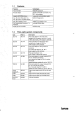
Table of contents 1. SURVEV 5 1.t Features 6 t.2 Fibre-optir system components 6 2. GENERAL 7 2.1 Funetion 7 2.2. Communication protorol 2.3 Type ofconnection 2.3 1 Fibre-optic riag 2.3.2 Fihre-optic network 7 8 8 9 2.4 Connection distanre lt 2.5 Plastic flbre-optic rables 12 2.5.1 2.5.2 2.5.3 2.5.4 Technical dass Csbtetypes Preparatioa ofeahtes Connection 12 t2 13 t3 2.5.5 Assembly 13 2.6 Number of partieipants 14 2.7 Commissioning 2.7. t Daager notes 2.7.2 Suppty vottage 2.7.
3.5 Plug-in power snpply linit part no. 362 016 3.5.1 Assembtv 3.5.
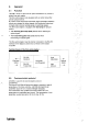
1. Survey LECOM-LI is a grnup et cennectinn elements te centrel the Lenze drive centrellers via plaatic tibre-optic cablea. The greup et LECOM-LI cnnnectien elements cemprises adaptnrs with optical tranamitters and nptical receivers, diatributers and pewer supply unit tor intercennecting plastic fibre-eptic cables.
1.1 Features Features Optical transfer Advantages best EMC protection 145-232 adaptor Supporte LECOM-5 protseol cbrectly connectable10 controller, PC, PLC. and processor reasonable communication system max. 52 units in tibre-opkc ring control 01 arge ptants max. 90 unlte in 1 Sre-optic networt< mao. 66 m between 2anIs equsls 3.4 km tengIh ot flog Can be separalnd by means 01 5 diatributor Supply by drivs controller 1.
2. General 2.1 Function LECOM-LI werks on the basis of optical transmission by means ot plastic tibre-optic cables. The tibre-optic adaptors are equipped with an optical tranamitter and an optical receiver. By meaes ot the electrooptic tranaducer (light tranamitter) electrical signals are changed to optical signals, the optoelectric transducer changes (light receiver) optical signals te electrical signals.
2.3 Type af cannectian LECOM-LI is the optical connection between the master computer and the drive controller. 2.3.1 Fibre-aptic ring A ring.shaped topology is used. The signals are transmitted to the next ring by means 01 an tibre-optic adaptor. The optical signal is amplitied by the fibre-optic adaptor and transmitted te the next component ot the ring. The TxD-lamp at Ihe tibre-optic adaptor flashes when an optical signal is amplified and transmitted and a signal is transmilted by the controller.
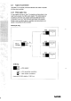
2.3.2 Fibre-optic netwark The tibre-optic distributor 2124 physically subdivides the fibre-optL eng in suorings and interconnects them to a network. tt is not necessary to assign all 4 subrings. Fibre.optic network 2125 Master computer — _i 0 2124 TxD xD TxD 1w~ 2122 TxD TxD~ 2122 ____ r-~-- ‚Controller 3 r Controller! 4 L 2122 - Dontroller Txt 1 5j __-J Erklärung: 1~1~D1 TxD RxD — = — LWL adaptor LWL transmitter connection LWL receiver connection 0 = LWL upperring 1 .
• • • The fibre-optic d~stributor transmits the signais (rom the tibra-optic top ring (channei 0) to all 4 fibre-optic subrings (channel 1-4)) and the signals from the 4 t;bre-optic subrings (channel 1 - 4) are tranamitted to the tibre-optic top ring (channel 0). You can connect either one, several or ne drive controllers to a fibre-optic subring.
2.4 Cannectian distance The maximum ttbre-optic cable length between two tibre-optic adaptore, dopende on • tranamitter‘s output • receivers sensitivity • tibre-optic cable attenuation. lt the transmission power ot the tibre-optic adaptor is too email, the signal will not ha received CIearly. lt the transmission power is tOo high, the signal will be overdriven. The cable attenuation depende on • tibre-optic cable quality • tibre-optic cable Iength • wave length. The wave length used 5 b6Onm.
2.5 Plastic fibre-aptic cables The eslension ot delivery does not Comprise plaatio tibre-opttt oables. They are standard produtts which are sold by most Cable suppliers. 2.5.1 Technical data The tibre-optit muat have the tollowing teatures: Fibre nore Polymelltyt mstbacryist IPMMAI 1? 878 pm (toteranos + 20 im) Fibra claoding Flsorise polymer 1? 1000 im (toleranne + 20 ym) Oder oheslh Thermopiastic polyester (PC) 2.20 mm Iloteranne u 0.07 mm) Bending radius Tensile streoglh min. 30 mm mao.
2.5.3 Preparation of cables • Gut cable to lcngth at right anglas an a rigid base using a sharp knite. Be aura to usa a good as naw blade (e.g. utility knife) • Remove 20 mm ot the rad PUR sheath, it presont. • Poliah ond ot tibre optic cable (grain = Pl 000). Note: With unpolishad tibre-optic Cable ends, the maximum Cable langth is typically reducad by 13 m (sf150 dB/km). A spetial )ibra-optic connector is not raquired. 2.5.
2.6 Number of participants To ensure best receiving quality tor tibre-optic adaptors, the number ot participants is limitert. All tibre-optic adaptors directly or indirectly connected 10 a master computer tibre-optic adaptor form a fibre-optic ring (see page 6). When using tibre-optic distributors, an tibre-optic network will be tormert
2.7 Commissioning 27.1 Danger notes Caution: 1. The opticar tibre can ha in)luertced by strong magnetic tields (e. g. busbars ot galvanic systems). 2. For external supply ot Ihe tibre-optic adaptors 2125 and 2126, pin 9 ot the sub-D socket may not be wired in the master computer, otherwise, the master computer can be dastroyad. 2.7.2 Supply voltage The tibre-optic adaptor at the drive controller is aupplied by the drive controller itselt.
2.7.4 Connection test We recommend to check the tibre-optic ring tor Commissioning the communication network LECOM-LI. Vou rio not need a master computer tor this test. After having completed the installation ot the tibre-optic network, Ihe tollowing fest helps to check the network: • Separate the fibre-optic adaptor 2125 or 2126 trom Ihe master drive. • Graste ahorting plug (bride 9 pole Sub-D-plug, pin 9 and pin 3 with lkD /aW). • Connect ahorting plug to tibre-opttc adaptor 2125 or 2126.
3. 3.1 Description of the units Fibre-optic adaptor 2121 tor 8100 E5 inverter series Fibre-optic adaptor 2121 in 8100 3.1.1 Assembly 1. De-energize the 8100 controller. 2. Assemble the tibre-optit adaptor 2121 direttly into the 8100 by means ot twa strews instead ot the Opole Sub-D connection. 3. Connect the enclosed ribbon Cable to the terminal connection X2 ot the 8100 POB. 4. Set tranamitter power by means ot the jumper (presetting: ‚min). 5. Connect tibre-optic cable.
3.1.2 Technical data Ccntrolicr type 8100 everter sories, cxc ca usse so Irom Biss E.5x.xx Ccntrcller plag lype MiCA10 by Lomberg Controierpin aoeignmsnt Fix 1 - NC Pin 2 - NC Contrcller nonneolon signale 145-232C )RxO x TeOl Controlier sopply Fibre-optin cable conneclion av OC xS%, max.70 mA Optical tranemitter Transaissios pomer nan be onangse Irom ~min In m50“; ~me“:typ. 50 pW = -13 dOm 1cr 0- 8 80 cable atleesalion man“: typ.
3.2 Fibre-optic adaptors 2122 and 2123 for all drive cofltrollers Fibre-optic adaptor 2122 or 2123 3.2.1 Assembly 1. De-enargize drive controller. 2. Connect the tibre-optic adaptor 2122 or 2123 to 9 pole SubD-connection ot the sertal interface X6 ot the drive controller. 3. Ccnnect the tibre-optic adaptor 2122 or 2123 to the controller housing by means ot 2 locking screws. 4. Connect fibre-optic cable.
3.2.2 Technical data Cnnlrotlor type 4900 4900 9100 A 8300 9500 9200 Controller connector type speie am 0-piog Controller pin aoaignmont Pin 1 Pin 2 Par3 Pie4 PieS Coelroller connector signal Controller sappty 145-232C 11400 ,- TxO) - St - TxO FoO -Nt -t,NO Pin 8 Pis 7 Pmb Po9 - NC - NC -Nt -+5V 5V OC at‘%, max. 70 mA Fibre-oytic cable cOnnectios Optinal tranemitter 2122 Pioch anram ixint tor libre-optic cable willi 2.2 mm ooter ojameler Transmission power „mm“: min. typ.
3.3 Fibre-optic distributor 2124 Fibre-optic distributor 2124 ~ 0 Erklärung: = LRxD 0 1 ... 4 =1= = = = = LWL-Sender-Anschlul3 LWL-Emptänger-Anschlul3 LWL-Obarring LWL-Unterring 1 bis 4 Versorgung 3.3.1 Assernbly 1. Fasten hie tibre-optit distributor 2124 on tha mounting plate. 2. Set transmission powerot the tibre-opticdistributor2l24 indivictually tor tha channal 0 - 4 by means ot tha jumper (presetting: „min‘). 3. Gonnett tibre-optit cable. 4.
3.3.2 Technical data Fibre-optin connoctioe PinoS screw jeint tor libro-optic cable willi 2.2 mm nutor diamoter OpScal Iranamittor Transmission power tor obannel 0 - 4 cxc 59 iadiaiooslly casrlgeo trum „min In „max“; „mm“.typ. 50 pW = -1 3dRm tor 0 - 8 d~ nable attenualon, max“: typ. 100 pW— IDdOm cr4- lOde cable attonoation l,ndicated is lire laonchod liglit power wite a Opbcsl roneiver aaad rate Signal disturtion Oirect raseining aopprossun Sappig Enolusure 22 maladisotmeal ut =5.
3.4 Fibre-optic adaptors 2125 and 2126 for master computer Fibre-optic adaptor 2125 or 2126 3.4.1 Assembly 1. De-energize master-computer. 2. Connect the tibre-optit adaptor 2125 or 2126 to the 9 pole Sub-D connection ot the serial interface ot hie serial interface (eg. COMI) ot the master Computer. 3. Connect the tibre-optic conneclor 2125 or 2126 to the master computer houstng by means ot 2 locking screws. 4. Gonnatt tibre-optic cable. 5.
3.4.2 Technical data Master cumpeter pleg type Ihn sssignmenl 9 pole Sub 0 plog Cunneotor eigasis Supyly R5-232C )14e0 x TeE)) 5V OC x5%, max. 70 mA xis 5s5-0-xocket enlernal eapply 9V Ot instable ur 9V - 12V Ot stable, max. 70 mA, xis 2,5 mm aok millt plespule allee nore )peak) Oplisal connector Pinolt onrore eint tor oplinal cable m:t5 2.2 mm nater eismeler Opliest Iranemitter 2125 Tranomiwion pomer „mm“; „mm“; typ.
3.5 Plug-in power supply unit part no. 362 016 The plug-in power supplv unit, part no. 362 016 ja usad torthe exlarnal powar supply 01 the tibra-optirz adaptor 2125 and 2126. Plug-in power Supply unlt 382 016 3.5.1 Assembly Gonnatt Ihe plug-in powar supply unil with the jarzk connaclion titted al tha side ot the tibre-optic adaplor. 2. Gonnett plug-in power supply unit to a horizontally titted mama socket outlat. 1. 3.5.
. Lenze in aller Welt Stammwerk Heed offlce Lanze GmbH & Co KG Puotlacir 10 13 82 0-31783 Hameln Meihsndnts Anfrfrbnnekoo M•chsniooi Dito. Oioolouor mroe• 3 0-nase encx 19l.loo 10515582-0 TodIm 1551 041 83.1812 Ksededeit nmeoe . e.roio• BeeI,m004, eeelaom 5±95.3 0-32eaa rme,na Telaim 051 041 a2-0 blaloo lt Ci ~ 82-r3se mdbU,raen schaue 0.71332 maslinsen Teeim nYrsrlaeaxs-x 59,eio lt 71 0115053520 EIdifroei•oti• AoOd•bmehm Elsobsein Dilsei hooe-L•ne.-sir.
Lanze GmbH & Co KG, Postfach 101352, D-31763 Hameln 1 Standort: Groß Berkel, Hans-Lanze-Straße 1 e D-31855 Aerzen, Telefon (051 54) 82-0 Telex 92853, Teletex 51 5411, Telefax (05154) 822111/822112, Telefax Service (05154) 822335 Printed in Germany by Lanze