
User Manual


Installation
4-3
BA2131EN
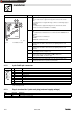
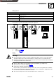
4.2 Mechanical installation
If a keypad is attached to the front of the controller, remove it.
Plug the 2131 fieldbus module in the corresponding interface of the controller and fasten it
with the fixing screw (
( 4-2) ,Fig.4-2,pos.7).
4.3 Electrical installation
Note!
The communciation of controllers 820X and 821X may be interfered by electromagnetic radiation.
If necessary, use an additional PE screen cable (
( 4-2) ,Fig.4-2,pos.9).
4.3.1 Voltage supply
If required, supply the 2131 fieldbus module via the plug-in contacts 1/2 ( ( 4-2) ,Fig.4-2,pos.6)
withaseparatevoltagesupply24VDC/10 %.
The 821X, 8200 vector, 822x and 93XX should always be driven without a separate voltage supply.
The controllers 820X (8201¤8204) always require a separte voltage supply!
Use a separate supply unit for the external voltage supply (24 V) of the 2131 fieldbus module.
Use separate supply units for longer distances between the control cabinets.
The following chapter describes how to connect the 2131 fieldbus module to the bus system, see
chapter 4.3.2.
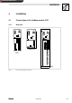
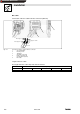
Note!
Internal voltage supply of the fieldbus module connected to a 8200 vector
Controllers with an extended AIF interface (front of the 8200 vector) can be internally supplied. The
part of the drawing highlighted with grey shows the jumper position.
In Lenze setting, the fieldbus module is not
internally supplied.
For internal voltage supply, put the jumper in the position indicated below.
Lenze setting
(only external voltage supply)
Internal voltage supply
Show/Hide Bookmarks