Automation Systems Controller 13461042 Ä.
Contents ________________________________________________________________ 1 1.1 1.2 1.3 1.
Contents ________________________________________________________________ 6 6.1 6.2 6.3 Parameter setting using »WebConfig« _ _ _ _ _ _ _ _ _ _ _ _ _ _ _ _ _ _ _ _ _ _ _ _ _ _ _ _ _ _ _ _ _ System structure _ _ _ _ _ _ _ _ _ _ _ _ _ _ _ _ _ _ _ _ _ _ _ _ _ _ _ _ _ _ _ _ _ _ _ _ _ _ _ _ _ _ _ _ _ Parameterising the controller _ _ _ _ _ _ _ _ _ _ _ _ _ _ _ _ _ _ _ _ _ _ _ _ _ _ _ _ _ _ _ _ _ _ _ _ _ _ Online connection from the Engineering PC to the controller _ _ _ _ _ _ _ _ _ _ _ _ _ _ _ _ _ _ _ _ 6.3.
Contents ________________________________________________________________ 11 Remote maintenance and diagnostics _ _ _ _ _ _ _ _ _ _ _ _ _ _ _ _ _ _ _ _ _ _ _ _ _ _ _ _ _ _ _ _ _ 11.1 Status LEDs of the Controllers _ _ _ _ _ _ _ _ _ _ _ _ _ _ _ _ _ _ _ _ _ _ _ _ _ _ _ _ _ _ _ _ _ _ _ _ _ 11.2 Diagnostics via Telnet _ _ _ _ _ _ _ _ _ _ _ _ _ _ _ _ _ _ _ _ _ _ _ _ _ _ _ _ _ _ _ _ _ _ _ _ _ _ _ _ _ _ 11.2.1 »WebConfig« settings _ _ _ _ _ _ _ _ _ _ _ _ _ _ _ _ _ _ _ _ _ _ _ _ _ _ _ _ _ _ _ _ _ _ _ _ _ 11.
Contents ________________________________________________________________ 13 Parameter reference _ _ _ _ _ _ _ _ _ _ _ _ _ _ _ _ _ _ _ _ _ _ _ _ _ _ _ _ _ _ _ _ _ _ _ _ _ _ _ _ _ _ _ 13.1 Structure of the parameter description _ _ _ _ _ _ _ _ _ _ _ _ _ _ _ _ _ _ _ _ _ _ _ _ _ _ _ _ _ _ _ _ 13.1.1 Data types _ _ _ _ _ _ _ _ _ _ _ _ _ _ _ _ _ _ _ _ _ _ _ _ _ _ _ _ _ _ _ _ _ _ _ _ _ _ _ _ _ _ _ 13.1.2 Parameters with read access _ _ _ _ _ _ _ _ _ _ _ _ _ _ _ _ _ _ _ _ _ _ _ _ _ _ _ _ _ _ _ _ _ 13.1.
1 About this documentation ________________________________________________________________ 1 About this documentation This documentation contains general information on how to parameterise, configure and diagnose the Lenze Controllers. This manual is part of the "Controller-based Automation" manual collection.
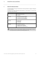
1 About this documentation ________________________________________________________________ More technical documentation for Lenze components Further information on Lenze products which can be used in conjunction with Controller-based Automation can be found in the following sets of documentation: Mounting & wiring Symbols: Mounting instructions • Controller • Communication cards (MC-xxx) • I/O system 1000 (EPM-Sxxx) • Inverter, Servo Drives • Communication modules Printed documentation Online h
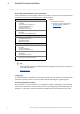
1 About this documentation ________________________________________________________________ Information regarding the validity The information provided in this documentation is valid for the following Lenze Controllers: Controller Versions Cabinet Controller • Controller 3221 C • Controller 3231 C • Controller 3241 C Example: Controller 3241 C with connected I/O system 1000 • Controller c300 Example: Controller c300 with connected I/O system 1000 Panel Controller • Controller p300 • Controller p500
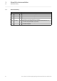
1 About this documentation 1.1 Document history ________________________________________________________________ 1.1 Document history Version 9 Description 1.0 10/2010 TD11 First edition for the Lenze automation system "Controller-based Automation" 3.x 1.1 04/2011 TD11 Update for the Lenze automation system "Controller-based Automation" 3.1 1.2 12/2011 TD11 Update for the Lenze automation system "Controller-based Automation" 3.2 1.
1 About this documentation 1.2 Conventions used ________________________________________________________________ 1.2 Conventions used This documentation uses the following conventions to distinguish between different types of information: Type of information Highlighting Examples/notes Spelling of numbers Decimal separators Point The decimal point is generally used. For example: 1234.
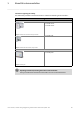
1 About this documentation 1.3 Terminology used ________________________________________________________________ 1.3 Terminology used Term Meaning Controller The controller is the central component of the automation system which controls the Logic and Motion functionalities by means of the runtime software. The controller communicates with the field devices via the fieldbus.
1 About this documentation 1.3 Terminology used ________________________________________________________________ Term Meaning EtherCAT® (Ethernet for Controller and Automation Technology) is an Ethernet-based fieldbus system which fulfils the application profile for industrial real-time systems. EtherCAT® is a registered trademark and patented technology, licensed by Beckhoff Automation GmbH, Germany.
1 About this documentation 1.4 Definition of the notes used ________________________________________________________________ 1.
2 Safety instructions ________________________________________________________________ 2 Safety instructions Please observe the following safety instructions when you want to commission an automation system or a plant using a controller.
3 Controller-based Automation: Central motion control ________________________________________________________________ 3 Controller-based Automation: Central motion control The Lenze automation system "Controller-based Automation" serves to create complex automation solutions with central motion control. Here, the Controller is the control centre of the system.
3 Controller-based Automation: Central motion control ________________________________________________________________ Lenze supply specially matched system components: • Engineering software The Lenze Engineering tools ( 20) on your Engineering PC (Windows® operating system) serve to parameterise, configure and diagnose the system. The Engineering PC communicates with the Controller via Ethernet.
3 Controller-based Automation: Central motion control ________________________________________________________________ Fieldbus communication The Lenze Controllers have different interfaces for fieldbus communication: Area Cabinet Controller c300 3221 C 3231 C Panel Controller 3241 C p300 p500 Interfaces (on board) Ethernet 1 2 1 2 EtherCAT 1 1) 1 1 1) 1 CANopen 1 2) - 1 2) - Optional interfaces (communication cards) CANopen MC-CAN2 - - PROFIBUS master MC-PBM - - PR
4 System structure ________________________________________________________________ 4 System structure This chapter provides you with an overview of the basic system structure of the Lenze "Controllerbased Automation" system. The system consists of an Engineering PC, a Controller and the devices communicating with the Controller via the fieldbus. [4-1] * The PROFIBUS fieldbus driver can only be accessed via PLC (Logic/Motion). Access via EASY Starter and VisiWinNET® Runtime is not provided.
4 System structure ________________________________________________________________ Note! There is no OPC server available for PROFIBUS and PROFINET. Controller c300/p300: • The »EASY Starter« cannot be used for these devices (in preparation). • The OPC communication for »VisiWinNET« is exclusively available for Controller p300 without PLC. • Otherwise, only the Lenze "Logic&Motion" direct driver can be used for the data exchange between »VisiWinNET« and PLC.
4 System structure 4.1 Engineering tools ________________________________________________________________ 4.1 Engineering tools The Engineering PC is a PC/Laptop with Windows® operating system and network connection. The Engineering PC comes installed with the Lenze Engineering tools which enable the desired automation solution to be ... • parameterised/configured; • programmed; • diagnosed. Lenze · Controller | Parameter setting & programming · Reference Manual · DMS 1.
4 System structure 4.1 Engineering tools ________________________________________________________________ »EASY Navigator«: Starting the suitable Engineering tool The Lenze Engineering software consists of the Engineering tools optimised for the respective Engineering phase. The »EASY Navigator« shows the Lenze Engineering tools installed on the Engineering PC. Start the desired Engineering tool via the corresponding button: The »EASY Navigator« ...
4 System structure 4.2 Controller: The control centre of the Controller-based Automation ________________________________________________________________ 4.2 Controller: The control centre of the Controller-based Automation Cabinet controllers: Compact control cabinet design Cabinet controllers are designed for the demanding continuous use in industrial applications. Compared to panel controllers, they are not equipped with an integrated display.
4 System structure 4.
4 System structure 4.3 Runtime software of the Lenze Controllers ________________________________________________________________ 4.3 Runtime software of the Lenze Controllers By default, the runtime software is installed in the Lenze Controller as "Logic" mode for the central control of PLC applications. Optionally, the "Motion" mode is available, additionally enabling extensive motion control of Motion functions. The inverter then only acts as an actuating drive.
4 System structure 4.3 Runtime software of the Lenze Controllers ________________________________________________________________ 4.3.1 "Logic" runtime software "Logic" refers to the use of logically combined control signals without Motion functions. When the "Logic" mode is used, the controller solely controls the motion sequences via logically combined control signals. Functionality • Programming PLC functionality according to IEC 61131-3. • SoftPLC functionality for executing PLC programs.
4 System structure 4.3 Runtime software of the Lenze Controllers ________________________________________________________________ 4.3.3 "Visu" runtime software The "Controller-based Automation" system enables the central visualisation of the automation system. The visualisation can either run on a separate Controller or monitor panel or on the Controller on which the "Logic" or "Motion" runtime software is running.
4 System structure 4.3 Runtime software of the Lenze Controllers ________________________________________________________________ 4.3.3.1 [4-2] Sample topology 1: External monitor panel/display for cabinet controllers Sample topology: Controller 3231 C with an external monitor panel (connected to the DVI interface) This topology with regard to its performance corresponds to the implemented solution (control/ visualisation on the same controller).
4 System structure 4.3 Runtime software of the Lenze Controllers ________________________________________________________________ 4.3.3.2 [4-3] Sample topology 2: Separate control and visualisation Sample topology: Controller 3200 C as gateway for the Visualisation Controller (IPC) The Visualisation Controller (IPC) accesses the field devices via the Controller 3200 C as gateway. In order to separate the control and visualisation, the integrated gateway function of the controller can be used.
4 System structure 4.3 Runtime software of the Lenze Controllers ________________________________________________________________ 4.3.3.3 [4-4] Sample topology 3: Independent control and visualisation (CANopen) Sample configuration: Parallel access of Controller 3200 C and Visualisation Controller (IPC) If this topology is used, the Controller 3200 C and the Visualisation Controller (IPC) access the fieldbus independently of each other.
5 Commissioning the controller ________________________________________________________________ 5 Commissioning the controller This chapter provides some general information on the commissioning of a controller. Depending on the actual hardware installed, different settings are required for integrating the controller into a network. Note! Please observe the predefined IP address of the controller for the initial commissioning: 192.168.5.99 (Lenze setting).
5 Commissioning the controller 5.1 Identification ________________________________________________________________ 5.1 Identification Note! Here the documentation provides some general information about the commissioning of a controller. Depending on the design and version of the controller, the commissioning process can be different. Every controller is provided with a nameplate containing the device data. The device data are helpful for identifying the technical equipment of the controller.
5 Commissioning the controller 5.3 Starting the controller ________________________________________________________________ 5.3 Starting the controller Note! During the starting process of the controller If a non-bootable USB flash drive is connected during the starting sequence, it will be stopped! • Remove the USB stick and restart the Controller. • Alternatively, the USB stick can be prepared using the »Backup & Restore« software.
5 Commissioning the controller 5.4 Configuring the controller ________________________________________________________________ 5.4 Configuring the controller This chapter provides information on how to configure the Controller during initial commissioning. The IP address setting is preserved after a restart of the system. 5.4.
5 Commissioning the controller 5.4 Configuring the controller ________________________________________________________________ 5.4.2.1 Cabinet controllers with external monitor panels (3231 C/3241 C) Note! If an external display (monitor panel) is used, the switch-on sequence of display/ controller must be observed so that it can be correctly controlled by the controller: • Connect the external display to the DVI output of the controller and switch it on before switching on the controller.
5 Commissioning the controller 5.4 Configuring the controller ________________________________________________________________ 5.4.2.2 Cabinet Controller without external monitor panel (c300/3221 C) To configure a Cabinet Controller without a connected monitor panel (e.g. Controller 3221 C), a PC/ laptop with the suitable addresses (IP address, subnet mask, default gateway) is required. • Connect the PC/laptop to the controller by means of a "crossed" network cable.
5 Commissioning the controller 5.4 Configuring the controller ________________________________________________________________ 5.4.3 Specifying the IP address of the controller via file (optional) How to proceed: 1. Create file "ip.txt" on the Engineering PC. 2. Save file "ip.txt" to the SD card of the controller by connecting the SD card to the Engineering PC using a memory card reader. File "ip.txt" 172.31.207.88 {IP address} 255.255.255.0 {subnet mask} 172.31.201.
5 Commissioning the controller 5.4 Configuring the controller ________________________________________________________________ 5.4.4 Establishing Windows® CE access rights In order to be able to establish a connection to the controller, each user has to be assigned access rights. For this the respective user has to be set up as a Windows® CE user with a user name and a password.
5 Commissioning the controller 5.4 Configuring the controller ________________________________________________________________ 5.4.5 Using your own wallpaper on the controller (Windows® CE) The standard wallpaper of the controller can be replaced by your own wallpaper. The wallpaper must meet the following conditions: • File format: bitmap (*.
5 Commissioning the controller 5.5 I/O system 1000 at the backplane bus of a cabinet controller ________________________________________________________________ 5.5 I/O system 1000 at the backplane bus of a cabinet controller The Cabinet Controllers 3200 C and c300 allow for a direct connection of the I/O system 1000 to the integrated backplane bus. The modules of the I/O system 100 connected to the backplane bus of the Controller can be parameterised in the »PLC Designer«. 5.5.
5 Commissioning the controller 5.5 I/O system 1000 at the backplane bus of a cabinet controller ________________________________________________________________ How to configure the I/O modules in the »PLC Designer«: 1. Append the I/O modules used as Devices to the I/O module coupler: Note: The sequence of the I/O modules in the device tree must comply with the physical arrangement. 2.
5 Commissioning the controller 5.5 I/O system 1000 at the backplane bus of a cabinet controller ________________________________________________________________ Use the I/O module coupler tab for diagnostics purposes using the PLC application. Example: Insert the b_myError variable in this tab. The variable is globally declared and the PLC application is able to evaluate it. 5.5.
5 Commissioning the controller 5.6 Tabs of the I/O modules at the backplane bus ________________________________________________________________ 5.6 Tabs of the I/O modules at the backplane bus The Workspace ... • uses various tabs to display the properties and settings of the module selected from the Device view. • serves to edit the parameters of the individual I/O compound modules. Depending on the module selected from the Device view, different tabs are available in the Workspace.
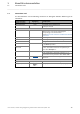
5 Commissioning the controller 5.7 Error messages (backplane bus) ________________________________________________________________ 5.7 Error messages (backplane bus) Error messages are represented on the Diagnostics tab of the I/O module coupler. [5-5] Example: Topology error, the EPM-S501 module cannot be reached at the backplane bus. Error messages The following error messages can be displayed: Error number 43 Error text/remedy 11 Too many I/O modules for the task cycle time selected.
5 Commissioning the controller 5.7 Error messages (backplane bus) ________________________________________________________________ Error number Error text/remedy 117 Read semaphore timeout for group 2 118 Read semaphore timeout for group 3 119 Write semaphore timeout for group 1 120 Write semaphore timeout for group 2 121 Write semaphore timeout for group 3 136 Configuration error in the I/O module topology. 137 Too many tasks for the processing of I/O modules.
6 Parameter setting using »WebConfig« 6.1 System structure ________________________________________________________________ 6 Parameter setting using »WebConfig« This chapter contains some information about the web-based parameterisation of the controller via »WebConfig«. 6.1 System structure 6.2 Parameterising the controller All settings that can be used for parameterising the controller are included in a numbered parameter list.
6 Parameter setting using »WebConfig« 6.3 Online connection from the Engineering PC to the controller ________________________________________________________________ 6.3 Online connection from the Engineering PC to the controller Connect the Engineering PC to the Controller using a network cable or connect the Controller to the network which is accessed to the Engineering PC.
6 Parameter setting using »WebConfig« 6.4 Start »WebConfig« ________________________________________________________________ The Properties of internet protocol (TCP/IP) dialog window How to set the browser: 1. Open the browser at the Engineering PC. (This setting refers to the Microsoft Internet Explorer.) 2. Select the Proxy settings dialog window: (ToolsInternet options ConnectionsSettingsAdvanced) 3. Position the cursor in the Exceptions field at the end of the entries available. 4.
6 Parameter setting using »WebConfig« 6.5 User interface of »WebConfig« ________________________________________________________________ 6.5 User interface of »WebConfig« The user interface of »WebConfig« is divided into the following areas - : Note! The representation of the user interface in area depends on the respective system configuration! Lenze · Controller | Parameter setting & programming · Reference Manual · DMS 1.
6 Parameter setting using »WebConfig« 6.
6 Parameter setting using »WebConfig« 6.5 User interface of »WebConfig« ________________________________________________________________ Representation of parameter values In the display area of »WebConfig«, settings of device parameters are represented with different background colours which have the following meaning: Colour Example Pale yellow Meaning Parameter (read only) • Display of status information and actual values.
6 Parameter setting using »WebConfig« 6.5 User interface of »WebConfig« ________________________________________________________________ 6.5.2 Diagnostic/device commands Button Diagnostics Function Displays parameters of the following areas: • Diagnostics • Logbook In the Logbook area you can configure settings regarding the Logbook.
6 Parameter setting using »WebConfig« 6.5 User interface of »WebConfig« ________________________________________________________________ 6.5.3 Logbook This user interface displays the logbook information of the Controller. The logbook offers various filter options to systematically display specific logbook contents. 6.5.3.
6 Parameter setting using »WebConfig« 6.5 User interface of »WebConfig« ________________________________________________________________ 6.5.3.2 6.5.3.3 Filter options Section Information Logbook Display logbook entries Structure of a logbook entry: example ( 52) Time period Select filter for the time period of the logbook entries shown • The logbook will only display entries which are in the selected time period.
6 Parameter setting using »WebConfig« 6.5 User interface of »WebConfig« ________________________________________________________________ 6.5.3.4 Saving log files with mains failure protection The log files are persisted automatically at certain events. Diagnostics with the logbook ( 89) You can also persist the log files manually by means of the »EASY Starter« and »WebConfig«. How to proceed: 1. Click the Device commands button. 2.
6 Parameter setting using »WebConfig« 6.5 User interface of »WebConfig« ________________________________________________________________ 6.5.4 Device commands In this area, the available device commands of parameter 18 (C0018) can be executed. Parameter 19 (C0019) shows status information relating to the executed command.
6 Parameter setting using »WebConfig« 6.5 User interface of »WebConfig« ________________________________________________________________ 6.5.7 Parameters of the communication cards This area of »WebConfig« displays the parameters of the installed communication cards. The following communication cards can be used: • MC-CAN2 • MC-PBM (PROFIBUS master) • MC-PBS (PROFIBUS slave) • MC-PND (PROFINET) A distinction is drawn between: • Interface parameters, • Communication card parameters.
6 Parameter setting using »WebConfig« 6.5 User interface of »WebConfig« ________________________________________________________________ 6.5.7.2 Optional PROFIBUS/PROFINET communication cards Button MC-xxx 6.5.8 Function MC-PBM: Parameter of the PROFIBUS master card communication card. MC-PBS: Parameter of the PROFIBUS slave card communication card. MC-PND: Parameter of the PROFINET communication card.
7 Programming with the »PLC Designer« ________________________________________________________________ 7 Programming with the »PLC Designer« This chapter provides you with general information on the programming of the control function of the controller. The »PLC Designer« is a Lenze Engineering tool for the creation of PLC programs according to IEC 61131.
7 Programming with the »PLC Designer« 7.1 System structure ________________________________________________________________ 7.1 System structure Install the »PLC Designer« on the Engineering PC. Via Ethernet, the »PLC Designer« accesses the Controller: 59 Lenze · Controller | Parameter setting & programming · Reference Manual · DMS 1.
7 Programming with the »PLC Designer« 7.2 Function blocks ________________________________________________________________ 7.2 Function blocks The »PLC Designer« contains function blocks which enable the PLC program to directly access the parameters of the Controller and the connected field devices. Parameters which can be accessed are ... • device parameters or logbook entries of the Controller; • device parameters of the field devices (example: Servo Inverter i700).
7 Programming with the »PLC Designer« 7.3 Configuring and parameterising the controller using the control application ________________________________________________________________ 7.3 Configuring and parameterising the controller using the control application For the creation of a control application, Lenze provides function blocks in standardised libraries (e.g.: motion functions according to PLCopen). Further function blocks can for instance be used to access controller parameters.
7 Programming with the »PLC Designer« 7.4 Controller c300/p300: Access to odd Controller addresses ________________________________________________________________ 7.4 Controller c300/p300: Access to odd Controller addresses Note! Due to the processor type (Cortex™-A8), write/read access of variables is only possible to memory addresses that are divisible by the variable size.
7 Programming with the »PLC Designer« 7.4 Controller c300/p300: Access to odd Controller addresses ________________________________________________________________ 2. In the case of many functions/function blocks, a pointer is transferred to a byte array and then the content of the byte array is for instance interpreted as DWORD. This requires manual conversion before the data are used: PROGRAM PLC_PRG PROGRAM PRG_Logic VAR mySDO_READ : CIA405.SDO_READ4; aReadData : ARRAY [1..
7 Programming with the »PLC Designer« 7.5 Creating remanent variables (retain/persistent) ________________________________________________________________ 7.5 Creating remanent variables (retain/persistent) Retain variables ... • are variables of the PLC which are automatically saved by the controller in the case of a voltage failure. • are variables which are necessary to restart the production process.
7 Programming with the »PLC Designer« 7.5 Creating remanent variables (retain/persistent) ________________________________________________________________ 7.5.1 Storage of retain data on the SD card (only Controllers 3221 C/3231 C) For Controllers 3221 C/3231 C, the values of the RETAIN variables are by default saved to the device only. • Use the L_Util_Retain function (from the L_Util.lib library) to save the RETAIN values to the SD card of the controllers.
7 Programming with the »PLC Designer« 7.5 Creating remanent variables (retain/persistent) ________________________________________________________________ Re-using remanent variables after a device replacement • A device replacement involves the insertion of the SD card of the replaced controller into the new device. • The boot application starts with the RETAIN values saved last by L_Util_Retain. • When the PLC is started, the RETAIN file is created once.
8 »Backup & Restore« (data backup/restore) ________________________________________________________________ 8 »Backup & Restore« (data backup/restore) The Lenze »Backup & Restore« software makes it possible to ... • create backups (data backup); • restore backups (data recovery); • install updates (update of the software/firmware of the Controller, only available for control technology). 67 Online help for »Backup & Restore« Here, further information can be found.
9 Data integrity in the event of a voltage failure 9.1 UPS functionality of the controllers ________________________________________________________________ 9 Data integrity in the event of a voltage failure 9.
9 Data integrity in the event of a voltage failure 9.1 UPS functionality of the controllers ________________________________________________________________ 9.1.2 External UPS (for Controllers 3241 C with UPS connection) The Controllers 3241 C provide for the connection of an external battery pack (ACCU-PACK) or capacitor pack (CAPS-PACK) to the X9 socket. Thus, voltage fluctuations of up to five seconds can be compensated for.
9 Data integrity in the event of a voltage failure 9.2 Storage of »VisiWinNET® Smart« visualisation data ________________________________________________________________ 9.2 Storage of »VisiWinNET® Smart« visualisation data The Controllers 3231 C cyclically store »VisiWinNET® Smart« visualisation data (user-specific trends, alarms, recipes) every 60 seconds.
9 Data integrity in the event of a voltage failure 9.3 Storage of retain/persistent variables of the PLC ________________________________________________________________ 9.
10 Device replacement - replacing the controller (in the event of service) ________________________________________________________________ 10 Device replacement - replacing the controller (in the event of service) Condition Principally, a defective Controller can only be replaced by a device of the same product type. Which replacement device is suitable for the Controller? ( 73) 10.
10 Device replacement - replacing the controller (in the event of service) ________________________________________________________________ 10.2 Connecting the new controller/replacement device Note! When a replacement device is connected, all communication cards which have been previously implemented and all terminals have to be selected identically. The user data are stored on the memory card of the controller.
10 Device replacement - replacing the controller (in the event of service) ________________________________________________________________ How to install and connect a new controller: 1. Insert the SD card of the removed controller into the new one. 2. Connect bus connections and other connections. 3. Connect the current supply of the controller. 4. If I/O modules (I/O system 1000) have to be connected to the controller: Plug in electronic module of the first system 1000 (if available). 5.
10 Device replacement - replacing the controller (in the event of service) ________________________________________________________________ 10.3 After the device replacement: Automatic data update When is an automatic data update possible? An automatic data update takes place after a defective Controller has been replaced by a replacement device.
10 Device replacement - replacing the controller (in the event of service) ________________________________________________________________ Undo update of the data (exceptional case) In the event of an accidental update, the initial state (version before the update) can be restored manually if a suitable backup is available. An "accidental" update takes place if an SD card has been plugged into a Controller which is not scheduled for replacement.
10 Device replacement - replacing the controller (in the event of service) ________________________________________________________________ 10.4 Subsequent use of retain data on the new controller Note! Depending on the used controller, the retain data of the PLC may no longer be available after a voltage failure/device replacement. • Controllers 3221 C/3231 C save the retain data internally (in the device, not on the SD card).
10 Device replacement - replacing the controller (in the event of service) ________________________________________________________________ 10.5 Error messages after a device replacement Message Information / remedy Backup/restore cannot be copied. Not enough free memory on the data medium. The SD card used has not enough free memory space to execute a safety backup. Delete non-required data from the SD card and try it again. The replacement device is not compatible with the original device.
11 Remote maintenance and diagnostics ________________________________________________________________ 11 Remote maintenance and diagnostics This chapter contains information on the Status LEDs of the Controllers ( 80) and the various diagnostics options for remote maintenance: Diagnostics via Telnet ( 82) Data transfer via FTP ( 85) Activate Windows® CE interface ( 92) Diagnostics with the logbook ( 89) Note! Error case: Controller c300/p300 does not start Information on error correction c
11 Remote maintenance and diagnostics 11.1 Status LEDs of the Controllers ________________________________________________________________ 11.1 Status LEDs of the Controllers The Controllers are provided with LEDs which indicate the current operating status. Depending on the Controller used, the colours of the LEDs vary.
11 Remote maintenance and diagnostics 11.1 Status LEDs of the Controllers ________________________________________________________________ LED Colour 1 / colour 2 green green Yellow Interval constantly on Meaning Controller is running (operating status): • PLC project is running (device is running, operating status) blinking (0.5 Hz) Starting process of the Controller active blinking (0.
11 Remote maintenance and diagnostics 11.2 Diagnostics via Telnet ________________________________________________________________ 11.2 Diagnostics via Telnet Telnet is a standard mechanism for experts to change system settings. Telnet ... • enables the access to the Controller data (example: Contents of the SD card); • requires an existing local connection or remote connection. Note! Controller c300/p300: • These devices come with a deactivated Telnet in the Lenze standard setting.
11 Remote maintenance and diagnostics 11.2 Diagnostics via Telnet ________________________________________________________________ 11.2.1 »WebConfig« settings The telnet settings can be configured via telnet parameters 180 to 181 by clicking the Remote maintenance button of the web-based parameterisation. • Parameter 180 activates authentication of the telnet user. • Parameter 181 activates the telnet access to the controller.
11 Remote maintenance and diagnostics 11.2 Diagnostics via Telnet ________________________________________________________________ How to establish a telnet connection to the controller: 1. Start the command line on the PC by means of which you want to log in, 2. Start buttonExecute, 3. Establish the telnet connection to the controller: Start telnet of the controller. 4.
11 Remote maintenance and diagnostics 11.3 Data transfer via FTP ________________________________________________________________ 11.3 Data transfer via FTP The File Transfer Protocol (FTP) is a network protocol for the transfer of data within networks. • FTP makes it possible to exchange files between the controller and other PCs. • The controller data can be accessed via FTP connection. • FTP requires an existing connection or a remote connection.
11 Remote maintenance and diagnostics 11.3 Data transfer via FTP ________________________________________________________________ 11.3.1 FTP settings with the »WebConfig« The settings of the FTP connection can be managed via the web-based parameterisation. From parameters 171 to 174 the FTP access for the controller can be activated and user rights can be specified.
11 Remote maintenance and diagnostics 11.3 Data transfer via FTP ________________________________________________________________ 11.3.2 FTP and web settings in the Internet Explorer Note! • You must change your browser settings to be able to establish an FTP / web connection to the controller. • Your firewall settings may be blocking your access via FTP and HTTP. Change your firewall settings or deactivate your firewall. • You need administrator rights to be able to change your firewall settings.
11 Remote maintenance and diagnostics 11.3 Data transfer via FTP ________________________________________________________________ Note! The settings for the local area network and the proxy settings depend on your own network settings on site. How to start an FTP connection to the controller: 1. Select the file transfer protocol in the input line of the web browser or in the command line via StartExecute...: 2. Enter: • FTP://:@.
11 Remote maintenance and diagnostics 11.4 Diagnostics with the logbook ________________________________________________________________ 11.4 Diagnostics with the logbook Lenze controllers are equipped with a logbook function which records system events and error messages. The entries in the logbook of the controller make it easier to diagnose the automation system if malfunctions occur. The logbook of the controller...
11 Remote maintenance and diagnostics 11.4 Diagnostics with the logbook ________________________________________________________________ 11.4.1 Logbook query via »WebConfig« The logbook entries can be called via »WebConfig«. • The browser of the Engineering PC accesses the web server of the controller via Ethernet connection (http://). • The data manager of the controller provides for access to logbook contents. How to call the logbook in »WebConfig«: 1.
11 Remote maintenance and diagnostics 11.4 Diagnostics with the logbook ________________________________________________________________ Logbook ( 52) 11.4.2 Logbook parameters The logbook settings can be called in »WebConfig« via the Diagnostics button.
11 Remote maintenance and diagnostics 11.5 Activate Windows® CE interface ________________________________________________________________ 11.5 Activate Windows® CE interface During normal operation the Windows® CE functions are hidden on the controller. All controller functions can be controlled via the Engineering PC. • For diagnostic purposes and maintenance activities you can use the standard functions of the controller operating system Windows® CE.
11 Remote maintenance and diagnostics 11.5 Activate Windows® CE interface ________________________________________________________________ How to activate the user interface of Windows® CE via telnet: 1. Log in on the controller which requires a diagnostics via Diagnostics via Telnet.
11 Remote maintenance and diagnostics 11.5 Activate Windows® CE interface ________________________________________________________________ 11.5.1 Remote Display: Remote control of Controller via Internet or LAN Remote Display Control for Windows® CE (cerhost/cerdisp) The Engineering PC requires the Remote Display Control software (cerhost.exe) which can be downloaded from the AKB on the Lenze homepage. It is also provided on the CD that is delivered along with the devices.
11 Remote maintenance and diagnostics 11.5 Activate Windows® CE interface ________________________________________________________________ 11.5.2 Virtual Network Computing (VNC) For the Engineering PC, you need the "Virtual Network Computing" (VNC) software. • VNC is preinstalled on the controller. (directory: \USBStorage\windows\VNC.exe) • VNC allows you to operate the controller by remote control from the Engineering PC.
12 Visualisation with »VisiWinNET®« ________________________________________________________________ 12 Visualisation with »VisiWinNET®« This chapter provides information about the Lenze Engineering tool »VisiWinNET®«. In addition to some basic information, you are provided with information with regard to the use of »VisiWinNET®« in connection with the "Controller-based Automation" system by Lenze. »VisiWinNET®« is a visualisation software for mechanical and systems engineering.
12 Visualisation with »VisiWinNET®« 12.1 Visualisation on the controller: local and remote ________________________________________________________________ 12.1 Visualisation on the controller: local and remote A visualisation can either run locally on a controller, or via remote connection on an additional controller. The following cases are distinguished: • Local visualisation - integrated control system Control and visualisation on the same controller.
12 Visualisation with »VisiWinNET®« 12.2 System structure ________________________________________________________________ 12.2 System structure »VisiWinNET®« consists of... • the »VisiWinNET®« Engineering tool on the Engineering PC: • the »VisiWinNET®« runtime on the Controller: and . By means of »VisiWinNET®« you create the visualisations on the Engineering PC. • The »VisiWinNET®« Engineering tool executes the associated »VisiWinNET®« runtime of the controller.
12 Visualisation with »VisiWinNET®« 12.3 Using the visualisation to access data of the control/parameters ________________________________________________________________ 12.3 Using the visualisation to access data of the control/parameters Variables of the PLC (Logic/Motion) can be accessed with the "LogicAndMotionV3" direct driver. Here, the »VisiWinNET®« Runtime may be on a local controller or on an external controller.
12 Visualisation with »VisiWinNET®« 12.3 Using the visualisation to access data of the control/parameters ________________________________________________________________ Communication type / description • CAN OPC tunnel • CAN Remote OPC tunnel (remote access) • EtherCAT OPC tunnel • EtherCAT Remote OPC tunnel (remote access) Note: The (Remote) SoftPLC OPC Tunnel communication type requires a separate configuration of the controller (experts only - please contact Lenze if required!).
12 Visualisation with »VisiWinNET®« 12.4 Use the Direct driver "LogicAndMotionV3" (local visualisation) ________________________________________________________________ 12.4 Use the Direct driver "LogicAndMotionV3" (local visualisation) We recommend the use of the "LogicAndMotionV3" direct driver for easy commissioning. Start »VisiWinNET®« Start the EASY »Navigator« Start »VisiWinNET® Smart« by clicking the Visualisation button. Note! There is no OPC server available for PROFIBUS and PROFINET.
12 Visualisation with »VisiWinNET®« 12.4 Use the Direct driver "LogicAndMotionV3" (local visualisation) ________________________________________________________________ 12.4.1 Selecting the target device using the Windows® CE operating system (example 3200 C/ p500) Using the "LogicAndMotionV3" direct driver. How to use the direct driver: 1. Create a new project in »VisiWinNET®«: File File New Project 2. Select the desired target device.
12 Visualisation with »VisiWinNET®« 12.4 Use the Direct driver "LogicAndMotionV3" (local visualisation) ________________________________________________________________ 4. Configure the added communication channel: • A Line must be activated and the PLC address (node address) of the Controller must be specified. • The PLC address and the IP address of the target device (Controller) must be specified. (Preset IP address of the Controller: 192.168.5.
12 Visualisation with »VisiWinNET®« 12.4 Use the Direct driver "LogicAndMotionV3" (local visualisation) ________________________________________________________________ 12.4.2 Project Explorer The project Explorer enables central access to controller data in »VisiWinNET®«. Select ViewProject Explorer in the menu bar to open the Project Explorer. Lenze · Controller | Parameter setting & programming · Reference Manual · DMS 1.
12 Visualisation with »VisiWinNET®« 12.4 Use the Direct driver "LogicAndMotionV3" (local visualisation) ________________________________________________________________ 12.4.3 Using the variables browser to access variables (browse variables) The variables browser can be used to browse for variables on the devices connected to the controller and to transfer them to a project subsequently.
12 Visualisation with »VisiWinNET®« 12.4 Use the Direct driver "LogicAndMotionV3" (local visualisation) ________________________________________________________________ 3. Click the Add button to select the desired communication type. Required information: Set line number (Line number), Devicealias (freely selectable), and the Parameterfile (XML symbol configuration file) exported from the »PLC Designer« V3.x.
12 Visualisation with »VisiWinNET®« 12.4 Use the Direct driver "LogicAndMotionV3" (local visualisation) ________________________________________________________________ 12.4.4 Accept variable definitions to project You can transfer one or more "browsed" variable definitions to your »VisiWinNET®« project. How to transfer the variable definitions to the project: 1. Highlight the desired device in the Devices selection list of the variables browser. 2. Click the OK button.
12 Visualisation with »VisiWinNET®« 12.4 Use the Direct driver "LogicAndMotionV3" (local visualisation) ________________________________________________________________ 12.4.5 Creating control elements/linking them to variables A user and visualisation interface created with »VisiWinNET®« consists of different control elements (e.g. buttons. checkboxes and selection fields). To be able to use control elements, the desired control elements must be linked to the available variables of the target device.
12 Visualisation with »VisiWinNET®« 12.4 Use the Direct driver "LogicAndMotionV3" (local visualisation) ________________________________________________________________ 12.4.6 Transferring an application to the target device In order to be able to transfer an application to the target device, you have to start the »VisiWinNET®« Remote Access Manager. For this purpose, activate parameter 97, "Activate VisiWinNET Remote Access " in »WebConfig«.
12 Visualisation with »VisiWinNET®« 12.4 Use the Direct driver "LogicAndMotionV3" (local visualisation) ________________________________________________________________ 12.4.7 Start the »VisiWinNET®« The »VisiWinNET®« Project Manager manages the »VisiWinNET®« project data of the target device (visualisation controller). Click the »VisiWinNET®« Project Manager icon to start the Project Manager.
12 Visualisation with »VisiWinNET®« 12.5 Using the LogicAndMotionV3 direct driver (remote access) ________________________________________________________________ 12.5 Using the LogicAndMotionV3 direct driver (remote access) Select the target device (Windows® XP operating system) Using the direct driver for LogicAndMotionV3.x under »VisiWinNET® Smart«. How to use the direct driver: 1. Select new project with the desired target device, example: Controller 3241C.
12 Visualisation with »VisiWinNET®« 12.6 OPC tunnel for local visualisation (integrated control system) ________________________________________________________________ 12.6 OPC tunnel for local visualisation (integrated control system) Note! There is no OPC server available for PROFIBUS and PROFINET. Controller c300/p300: • The OPC communication for »VisiWinNET« is exclusively available for Controller p300 without PLC.
12 Visualisation with »VisiWinNET®« 12.6 OPC tunnel for local visualisation (integrated control system) ________________________________________________________________ 12.6.1 Integrating the OPC tunnel in »VisiWinNET®« The OPC tunnel is the communication channel between »VisiWinNET®« and the OPC servers of the controller. The desired OPC tunnel must be integrated into the project. Note! The OPC tunnel cannot be integrated by means of the menu navigation (during the creation of a new project).
12 Visualisation with »VisiWinNET®« 12.6 OPC tunnel for local visualisation (integrated control system) ________________________________________________________________ 12.6.2 Browsing variable definitions / configuring the device When you have started the Lenze Variables Browser, you can configure one or more devices and then import the variable definitions. How to browse for variable definitions: 1. Click the Add button in the Lenze Variables Browser: 2.
12 Visualisation with »VisiWinNET®« 12.6 OPC tunnel for local visualisation (integrated control system) ________________________________________________________________ Communication types 115 Communication type Description DataManager OPC tunnel Required information: • Devicealias • Parameterfile Supported file formats: • Device description files (*.dcf, *.eds) Suitable device description files (*.
12 Visualisation with »VisiWinNET®« 12.6 OPC tunnel for local visualisation (integrated control system) ________________________________________________________________ 12.6.3 Manual integration of variables (experts only - background knowledge required!) If no suitable parameter file is available, the Item ID can also be entered manually (as an alternative to the variables browser). Depending on the server and the type of connection (local or remote), a defined syntax must be observed.
12 Visualisation with »VisiWinNET®« 12.6 OPC tunnel for local visualisation (integrated control system) ________________________________________________________________ Access to ... 117 Syntax of the ItemID CAN Remote OPC tunnel 1. In the ItemID, put the prefix, , in front. 2. Specify the variable as follows: CAN.can.dev.pari<0x5FFF "minus" Code>d.
12 Visualisation with »VisiWinNET®« 12.6 OPC tunnel for local visualisation (integrated control system) ________________________________________________________________ Data types The following data types are available for query: Data type Description »VisiWinNET®« OPC tunnel VT_BOOL d11 Truth value (TRUE/FALSE) VT_BSTR d8 String STRING VT_DATE d7 Date / time format VT_EMPTY d0 The data type is not specified. • This data type is e.g. returned if no process variable has been specified.
12 Visualisation with »VisiWinNET®« 12.6 OPC tunnel for local visualisation (integrated control system) ________________________________________________________________ 12.6.4 Configure OPC tunnel The OPC tunnel ... • permits »VisiWinNET®« access to the OPC servers of the Controller • "tunnels" all accesses via a special Ethernet port and hence offers the possibility of remote access by security systems.
12 Visualisation with »VisiWinNET®« 12.7 OPC tunnel for external visualisation (remote access) ________________________________________________________________ 12.7 OPC tunnel for external visualisation (remote access) 12.7.1 Windows® CE operating system The »VisiWinNET®« Runtime of the external controller, Controller(Visu), accesses the OPC servers of the control system Controller via the OPC tunnels (1, 2).
12 Visualisation with »VisiWinNET®« 12.7 OPC tunnel for external visualisation (remote access) ________________________________________________________________ 12.7.1.1 Configure OPC tunnel for remote access (Windows® CE) For the configuration of the OPC tunnel, the oct.xml configuration file must be edited. In our example, the IP address of the Controller controller is: 192.168.5.99 • For configuring OPC tunnel 1, use the oct.xml configuration file in the \USBStorage\OCT storage\OCT directory.
12 Visualisation with »VisiWinNET®« 12.7 OPC tunnel for external visualisation (remote access) ________________________________________________________________ 12.7.2 Windows® XP/XP Embedded operating system The »VisiWinNET®« runtime of the external Windows® XP/XP Embedded controller accesses (via OPC tunnel 1) the OPC servers of the Controller. Note! There is no OPC server available for PROFIBUS and PROFINET.
12 Visualisation with »VisiWinNET®« 12.7 OPC tunnel for external visualisation (remote access) ________________________________________________________________ 12.7.2.1 Configure OPC tunnel for remote access (Windows® XP/XP Embedded) In our example, the IP address of the Controller is: 192.168.5.99 • For the configuration of OPC tunnel 1 (external Controller), the oct.xml configuration file is used which can be found in the \Programs\Lenze\Lenze Digitec OPC Tunnel directory.
12 Visualisation with »VisiWinNET®« 12.7 OPC tunnel for external visualisation (remote access) ________________________________________________________________ 12.7.3 Browsing variables This chapter describes how to browse variables using the Remote OPC tunnel. How to browse for variable definitions: 1. Click the Add button to import the variable definition file which has been previously exported from the »PLC Designer«.
12 Visualisation with »VisiWinNET®« 12.7 OPC tunnel for external visualisation (remote access) ________________________________________________________________ 125 Communication type Description EtherCAT Remote OPC tunnel Required information: • Remote name of the target device (example: "RemoteIPC") • EtherCAT interface (EtherCAT Interface) • EtherCAT address (EtherCAT Node Address) • Devicealias • Parameterfile Supported file format: • Device description files (*.dcf, *.
12 Visualisation with »VisiWinNET®« 12.8 Lenze specifications ________________________________________________________________ 12.8 Lenze specifications 12.8.1 Install additional fonts How to install additional fonts for visualisation: 1. Copy the additional font file to the \USBStorage\Fonts directory on the SD card. 2. In the PostStart.txt file, add the AddFont.exe entry. The PostStart.txt file is in the \USBStorage directory (basic directory of the SD card). 12.8.
13 Parameter reference ________________________________________________________________ 13 Parameter reference This chapter provides a list of all controller parameters in numerically ascending order. Note! Depending on the configuration and assembly of your controller, the parameter lists may vary.
13 Parameter reference 13.1 Structure of the parameter description ________________________________________________________________ 13.
13 Parameter reference 13.1 Structure of the parameter description ________________________________________________________________ 13.1.2 Parameters with read access Parameters without the "Write access" attribute are read only/not editable. Description structure Parameter | Name: Data type: _______ Index: _______ Cxxxxx | _____________ Descriptive text Display range (min. value | unit | max. value) Read access Write access CINH PLC-STOP No transfer 13.1.
13 Parameter reference 13.1 Structure of the parameter description ________________________________________________________________ 13.1.3.3 Parameters with a bit-coded setting Description structure Parameter | Name: Data type: _______ Index: _______ Cxxxxx | _____________ Descriptive text Value is bit-coded: Bit 0 ... Bit 31 Read access Write access CINH PLC-STOP No transfer 13.1.4 Parameter attributes Attribute Meaning Read access Read access to parameter possible.
13 Parameter reference 13.2 Basic parameters of the Controllers 3200 C/c300 and p300/p500 ________________________________________________________________ 13.2 Basic parameters of the Controllers 3200 C/c300 and p300/p500 In this chapter all parameters of the controller standard devices (Cabinet Controller/Panel Controller) are listed in numerically ascending order.
13 Parameter reference 13.
13 Parameter reference 13.
13 Parameter reference 13.2 Basic parameters of the Controllers 3200 C/c300 and p300/p500 ________________________________________________________________ C0042 Parameter | Name: Data type: UNSIGNED_32 Index: 24533d = 5FD5h C0042 | Number of reboots Number of boot processes of the device Display range (min. value | unit | max.
13 Parameter reference 13.2 Basic parameters of the Controllers 3200 C/c300 and p300/p500 ________________________________________________________________ C0051 Parameter | Name: Data type: UNSIGNED_32 Index: 24524d = 5FCCh C0051 | Logbook: Size on CF Size of the memory space occupied on the SD memory card Display range (min. value | unit | max.
13 Parameter reference 13.2 Basic parameters of the Controllers 3200 C/c300 and p300/p500 ________________________________________________________________ C0056 Parameter | Name: Data type: UNSIGNED_32 Index: 24519d = 5FC7h C0056 | Logbook: Index of last entry on CF Number of the last entry on the SD memory card Display range (min. value | unit | max.
13 Parameter reference 13.2 Basic parameters of the Controllers 3200 C/c300 and p300/p500 ________________________________________________________________ C0071 Parameter | Name: Data type: UNSIGNED_32 Index: 24504d = 5FB8h C0071 | Allocated program memory Size of the reserved program memory Display range (min. value | unit | max.
13 Parameter reference 13.2 Basic parameters of the Controllers 3200 C/c300 and p300/p500 ________________________________________________________________ C0079 Parameter | Name: Data type: UNSIGNED_32 Index: 24496d = 5FB0h C0079 | Used flash memory Flash memory occupied Display range (min. value | unit | max.
13 Parameter reference 13.2 Basic parameters of the Controllers 3200 C/c300 and p300/p500 ________________________________________________________________ C0092 139 Lenze · Controller | Parameter setting & programming · Reference Manual · DMS 1.
13 Parameter reference 13.2 Basic parameters of the Controllers 3200 C/c300 and p300/p500 ________________________________________________________________ Lenze · Controller | Parameter setting & programming · Reference Manual · DMS 1.
13 Parameter reference 13.2 Basic parameters of the Controllers 3200 C/c300 and p300/p500 ________________________________________________________________ Parameter | Name: Data type: VISIBLE_STRING Index: 24483d = 5FA3h C0092 | Time zone Time zone of the device. Possible values: "Central European Standard Time", "North Pacific Standard Time", "GMT Standard Time", ...
13 Parameter reference 13.
13 Parameter reference 13.2 Basic parameters of the Controllers 3200 C/c300 and p300/p500 ________________________________________________________________ Parameter | Name: Data type: VISIBLE_STRING Index: 24483d = 5FA3h C0092 | Time zone Myanmar Standard Time Myanmar Standard Time N. Central Asia Standard N.
13 Parameter reference 13.
13 Parameter reference 13.2 Basic parameters of the Controllers 3200 C/c300 and p300/p500 ________________________________________________________________ C0100 Parameter | Name: Data type: UNSIGNED_8 Index: 24475d = 5F9Bh C0100 | WinCe users: Number Number of users registered Display range (min. value | unit | max.
13 Parameter reference 13.2 Basic parameters of the Controllers 3200 C/c300 and p300/p500 ________________________________________________________________ C0106 Parameter | Name: Data type: UNSIGNED_8 Index: 24469d = 5F95h C0106 | WinCE-User: User 1 with telnet permissions User may use telnet Setting range (min. value | unit | max.
13 Parameter reference 13.2 Basic parameters of the Controllers 3200 C/c300 and p300/p500 ________________________________________________________________ C0113 Parameter | Name: Data type: UNSIGNED_8 Index: 24462d = 5F8Eh C0113 | WinCE user: User 2 with telnet permissions User may use telnet Setting range (min. value | unit | max.
13 Parameter reference 13.2 Basic parameters of the Controllers 3200 C/c300 and p300/p500 ________________________________________________________________ C0120 Parameter | Name: Data type: UNSIGNED_8 Index: 24455d = 5F87h C0120 | WinCE user: User 3 with telnet permissions User may use telnet Setting range (min. value | unit | max.
13 Parameter reference 13.2 Basic parameters of the Controllers 3200 C/c300 and p300/p500 ________________________________________________________________ C0127 Parameter | Name: Data type: UNSIGNED_8 Index: 24448d = 5F80h C0127 | WinCE users: User 4 with telnet permissions User may use telnet Setting range (min. value | unit | max.
13 Parameter reference 13.2 Basic parameters of the Controllers 3200 C/c300 and p300/p500 ________________________________________________________________ C0134 Parameter | Name: Data type: UNSIGNED_8 Index: 24441d = 5F79h C0134 | WinCE users: User 5 with telnet permissions User may use telnet Setting range (min. value | unit | max.
13 Parameter reference 13.2 Basic parameters of the Controllers 3200 C/c300 and p300/p500 ________________________________________________________________ C0141 Parameter | Name: Data type: UNSIGNED_8 Index: 24434d = 5F72h C0141 | WinCE users: User 6 with telnet permissions User may use telnet Setting range (min. value | unit | max.
13 Parameter reference 13.2 Basic parameters of the Controllers 3200 C/c300 and p300/p500 ________________________________________________________________ C0148 Parameter | Name: Data type: UNSIGNED_8 Index: 24427d = 5F6Bh C0148 | WinCE users: User 7 with telnet permissions User may use telnet Setting range (min. value | unit | max.
13 Parameter reference 13.2 Basic parameters of the Controllers 3200 C/c300 and p300/p500 ________________________________________________________________ C0155 Parameter | Name: Data type: UNSIGNED_8 Index: 24420d = 5F64h C0155 | WinCE users: User 8 with telnet permissions User may use telnet Setting range (min. value | unit | max.
13 Parameter reference 13.2 Basic parameters of the Controllers 3200 C/c300 and p300/p500 ________________________________________________________________ C0162 Parameter | Name: Data type: UNSIGNED_8 Index: 24413d = 5F5Dh C0162 | WinCE users: User 9 with telnet permissions User may use telnet Setting range (min. value | unit | max.
13 Parameter reference 13.2 Basic parameters of the Controllers 3200 C/c300 and p300/p500 ________________________________________________________________ C0169 Parameter | Name: Data type: UNSIGNED_8 Index: 24406d = 5F56h C0169 | WinCE users: User 10 with telnet permissions User may use telnet Setting range (min. value | unit | max.
13 Parameter reference 13.2 Basic parameters of the Controllers 3200 C/c300 and p300/p500 ________________________________________________________________ C0181 Parameter | Name: Data type: UNSIGNED_32 Index: 24394d = 5F4Ah C0181 | Telnet: Enabled Activation of the telnet service • Entering "1" activates the telnet service • Entering "0" deactivates the telnet service Setting range (min. value | unit | max.
13 Parameter reference 13.2 Basic parameters of the Controllers 3200 C/c300 and p300/p500 ________________________________________________________________ C0187 Parameter | Name: Data type: VISIBLE_STRING Index: 24388d = 5F44h C0187 | Visualisation licence Visualisation licence (relevant for the visualisation in VisiWinNET).
13 Parameter reference 13.3 Voltage buffering by external UPS (optional, for Controller 3241 C) ________________________________________________________________ 13.3 Voltage buffering by external UPS (optional, for Controller 3241 C) This chapter lists all UPS parameters in numerically ascending order.
13 Parameter reference 13.3 Voltage buffering by external UPS (optional, for Controller 3241 C) ________________________________________________________________ C0207 Parameter | Name: Data type: FLOAT_32 Index: 24368d = 5F30h C0207 | UPS: Battery / capacitor voltage Voltage of the battery/capacitor in [V] Display range (min. value | unit | max.
13 Parameter reference 13.
13 Parameter reference 13.4 Ethernet (on board) ________________________________________________________________ 13.4 Ethernet (on board) This chapter provides a list of all parameters of the Ethernet interface (on board) of the controllers in numerically ascending order. C0238 Parameter | Name: Data type: UNSIGNED_16 Index: 24337d = 5F11h C0238 | Apply IP configuration Parameter for the activation of the set IP configuration.
13 Parameter reference 13.4 Ethernet (on board) ________________________________________________________________ C0244 Parameter | Name: C0244 | Domain Data type: VISIBLE_STRING Index: 24331d = 5F0Bh Domain name of the interface Read access Write access CINH PLC-STOP No transfer C0246 Parameter | Name: C0246 | MAC address Data type: VISIBLE_STRING Index: 24329d = 5F09h MAC address (6 8-bit hexadecimal numbers) (e.g.
13 Parameter reference 13.5 EtherCAT ________________________________________________________________ 13.5 EtherCAT This chapter provides a list of all EtherCAT parameters of the EtherCAT interface (on board) of the Controllers and the EtherCAT communication card MC-ETC in numerically ascending order. C280/4 Parameter | Name: Data type: UNSIGNED_8 Index: 24295.4d = 0x5EE7.
13 Parameter reference 13.5 EtherCAT ________________________________________________________________ C281/5 Parameter | Name: Data type: UNSIGNED_32 Index: 24294.5d = 0x5EE6.0x05h C281/5 | ECAT master: State information Display of additional information on the current state of the master The bits are set to value 1 if the respective states are reached.
13 Parameter reference 13.5 EtherCAT ________________________________________________________________ C282/3 Parameter | Name: Data type: INTEGER_32 Index: 24293.3d = 0x5EE5.0x03h C282/3 | - ECAT DC: Current deviation Current maximum deviation of the distributed clocks of all devices in nanoseconds. Display range (min. value | unit | max. value) -2147483647 ns 2147483647 Read access Write access CINH PLC-STOP No transfer C286/3 Parameter | Name: Data type: UNSIGNED_32 Index: 24289.
13 Parameter reference 13.5 EtherCAT ________________________________________________________________ C286/7 Parameter | Name: Data type: UNSIGNED_32 Index: 24289.7d = 0x5EE1.0x07h C286/7 | ECAT counter: Tx frames Number of sent frames Display range (min. value | unit | max. value) 0 4294967295 Read access Write access CINH PLC-STOP No transfer C286/8 Parameter | Name: Data type: UNSIGNED_32 Index: 24289.8d = 0x5EE1.
13 Parameter reference 13.5 EtherCAT ________________________________________________________________ C286/12 Parameter | Name: Data type: UNSIGNED_32 Index: 24289.12d = 0x5EE1.0x0Ch C286/12 | ECAT counter: acyclical frames Number of acyclical frames Display range (min. value | unit | max. value) 0 4294967295 Read access Write access CINH PLC-STOP No transfer C286/13 Parameter | Name: C286/13 | ECAT counter: acyclical datagrams Data type: UNSIGNED_32 Index: 24289.13d = 0x5EE1.
13 Parameter reference 13.6 Monitor panel (integrated/external) ________________________________________________________________ 13.6 Monitor panel (integrated/external) This chapter lists all parameters of the monitor panel (panel controller) and the parameters of an external, optional panel in numerically ascending order. The parameters are available depending on the panel variant.
13 Parameter reference 13.6 Monitor panel (integrated/external) ________________________________________________________________ C0424 Parameter | Name: Data type: UNSIGNED_8 Index: 24151d = 5E57h C0424 | Automatic dimout: Switch-on after Enter the time until automatic dimout of the display. The values range between ... • ... 0 (maximum value = no dimout of the display) and • ...
13 Parameter reference 13.6 Monitor panel (integrated/external) ________________________________________________________________ C0433 Parameter | Name: Data type: VISIBLE_STRING Index: 24142d = 5E4Eh C0433 | F1 key: Parameter Name of the program or script to be executed • Applies to external monitor panels with function keys.
13 Parameter reference 13.6 Monitor panel (integrated/external) ________________________________________________________________ C0437 Parameter | Name: Data type: VISIBLE_STRING Index: 24138d = 5E4Ah C0437 | F3 key: Parameter Name of the program or script to be executed • Applies to external monitor panels with function keys.
13 Parameter reference 13.7 PLC (Logic/Motion) ________________________________________________________________ 13.7 PLC (Logic/Motion) In this chapter the parameters of the PLC (Logic/Motion) are listed in numerically ascending order.
13 Parameter reference 13.
13 Parameter reference 13.8 Backup&Restore ________________________________________________________________ 13.8 Backup&Restore In this chapter, all parameters for carrying out a »Backup & Restore« (using »WebConfig«) are listed in numerically ascending order.
13 Parameter reference 13.
13 Parameter reference 13.
13 Parameter reference 13.8 Backup&Restore ________________________________________________________________ C0833 Parameter | Name: C0833 | Restore update status Data type: VISIBLE_STRING Index: 23742d = 5CBEh Read access Write access CINH PLC-STOP No transfer 177 Lenze · Controller | Parameter setting & programming · Reference Manual · DMS 1.
13 Parameter reference 13.9 Communication cards: optional interface ________________________________________________________________ 13.9 Communication cards: optional interface This chapter provides you with some information about the parameters of the optional controller communication cards. The communication cards allow for a use of the controller with further bus systems. EtherCAT is the "on board" standard bus system of the Controllers. Note! Controllers c300/p300 ...
13 Parameter reference 13.9 Communication cards: optional interface ________________________________________________________________ 13.9.1 CAN (MC-CAN2) communication card / CAN interface for Controller c300/p300 This chapter provides a list of all parameters of the communication card and the CAN interface of the Controllers c300/p300 in numerically ascending order. The MC-CAN2 communication card ... • has two CAN connections/interfaces; • is not supported by the Controllers c300/p300.
13 Parameter reference 13.
13 Parameter reference 13.9 Communication cards: optional interface ________________________________________________________________ C1082 Parameter | Name: Data type: UNSIGNED_32 Index: 23493d = 5BC5h C1082 | Baud rate Baud rate of the CAN interface. The value is assigned from a selection list.
13 Parameter reference 13.9 Communication cards: optional interface ________________________________________________________________ C1093 Parameter | Name: Data type: UNSIGNED_32 Index: 23482d = 5BBAh C1093 | Error counter Error counter since last initialisation of the CAN interface Display range (min. value | unit | max.
13 Parameter reference 13.9 Communication cards: optional interface ________________________________________________________________ C1121 Parameter | Name: Data type: UNSIGNED_32 Index: 23454d = 5B9Eh C1121 | Sync master: Interface index Note: Restart the L-force Controller after changing this parameter! Setting range (min. value | unit | max.
13 Parameter reference 13.9 Communication cards: optional interface ________________________________________________________________ C1132 Parameter | Name: Data type: UNSIGNED_32 Index: 23443d = 5B93h C1132 | Bus load Specification of the average bus load. The bus load is calculated as follows: Bus load = Value in percent x 1000 Display range (min. value | unit | max.
13 Parameter reference 13.9 Communication cards: optional interface ________________________________________________________________ 13.9.2 PROFIBUS and PROFINET communication cards This chapter provides a list of all parameters of the PROFINET IO/ device (MC-PND) and PROFIBUS master/slave (MC-PBM/MC-PBS) communication cards in numerically ascending order.
13 Parameter reference 13.9 Communication cards: optional interface ________________________________________________________________ C1038 Parameter | Name: C1038 | Device: Manufacturing date Data type: VISIBLE_STRING Index: 23537d = 5BF1h Manufacturing date of the card Read access Write access CINH PLC-STOP No transfer Lenze · Controller | Parameter setting & programming · Reference Manual · DMS 1.
Index ________________________________________________________________ 0 ...
Index ________________________________________________________________ C125 148 C126 148 C127 149 C129 149 C13 131 C130 149 C131 149 C132 149 C133 149 C134 150 C136 150 C137 150 C138 150 C139 150 C140 150 C141 151 C143 151 C144 151 C145 151 C146 151 C147 151 C148 152 C15 132 C150 152 C151 152 C152 152 C153 152 C154 152 C155 153 C157 153 C158 153 C159 153 C16 132 C160 153 C161 153 C162 154 C164 154 C165 154 C166 154 C167 154 C168 154 C169 155 C172 155 C173 155 C174 155 C18 132 C180 155 C181 156 C182 156 C183
Index ________________________________________________________________ C425 169 C426 169 C43 134 C432 169 C433 170 C434 170 C435 170 C436 170 C437 171 C438 171 C439 171 C48 134 C49 134 C5 131 C50 134 C51 135 C52 135 C53 135 C54 135 C55 135 C56 136 C57 136 C58 136 C6 131 C620 172 C630 172 C64 136 C640 172 C650 172 C651 172 C660 173 C661 173 C7 131 C70 136 C71 137 C72 137 C75 137 C76 137 C78 137 C79 138 C8 131 C809 174 C810 174 C811 174 C813 174 189 C814 175 C815 175 C816 175 C817 175 C818 175 C819 175 C820
Index ________________________________________________________________ D Data transfer via FTP 85 Data types 128 Default gateway (C243) 161 Device Driver index (C1073) 180 Driver index (C1113) 182 Hardware version (C1035) 179, 185 Hardware version (C5) 131 Identification (C1031) 179, 185 Manufacturer (C1037) 180, 185 Manufacturer (C7) 131 Manufacturing date (C1038) 180, 186 Manufacturing date (C8) 131 Name (C1033) 179, 185 Name (C3) 131 Serial number (C1036) 180, 185 Serial number (C6) 131 Software version
Index ________________________________________________________________ I O I/O compound module, tab 42 I/O modules at the backplane bus 39 Identification of the Controller 31 Identification of the controller 31 Interfaces for fieldbus communication 17, 23 IP address (C241) 161 Online connection between the Engineering PC and Industrial PC 46 OPC tunnel for external visualisation 120 Operating systems of the Controllers 60 Operating time (C41) 133 L Panel Height (C421) 168 Width (C420) 168 Panel Contro
Index ________________________________________________________________ S U Safety 14 Safety instructions 13 Screenshots 7 Select a backup or update (C824) 176 Select a main action for the Lenze software (C809) 174 Select a main action for the Lenze software (C810) 174 Selecting the IP address of the controller: With file 36 Setting IP addresses 46 Settings in the »WebConfig« 83 Software (Engineering tools) 20 Start backup (C830) 176 Start Field Device parameter storage (C650) 172 Start Field Device param
Index ________________________________________________________________ W Web settings in the Internet Explorer 87 WebConfig - user interface 48 WinCe users Number (C100) 145 Password 1 (C102) 145 Password 10 (C165) 154 Password 2 (C109) 146 Password 3 (C116) 147 Password 4 (C123) 148 Password 5 (C130) 149 Password 6 (C137) 150 Password 7 (C144) 151 Password 8 (C151) 152 Password 9 (C158) 153 User 1 with FTP permissions (C103) 145 User 1 with telnet permissions (C106) 146 User 10 with FTP permissions (C166)
)(('%$&. Your opinion is important to us These instructions were created to the best of our knowledge and belief to give you the best possible support for handling our product. Perhaps we have not succeeded in achieving this objective in every respect. If you have suggestions for improvement, please e-mail us to: feedback-docu@lenze.com Thank you very much for your support.
Controller | Parameter setting & programming · Reference Manual · SHGPCBAUTO-001 · 13461042 · DMS 1.5 EN · 04/2014 · TD17 Lenze Automation GmbH Postfach 10 13 52, D-31763 Hameln Hans-Lenze-Straße 1, D-31855 Aerzen Germany +49 5154 82-0 +49 5154 82-2800 lenze@lenze.com www.lenze.com Service Lenze Service GmbH Breslauer Straße 3, D-32699 Extertal Germany 008000 24 46877 (24 h helpline) +49 5154 82-1112 service@lenze.