
User guide


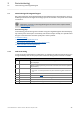


Table Of Contents
- Inverter Drives 8400 BaseLine C
- Overview of technical documentation for Inverter Drives 8400
- Contents
- 1 About this documentation
- 2 Introduction: Parameterising the controller
- 3 Commissioning
- 4 Device control (DCTRL)
- 5 Motor control (MCTRL)
- 5.1 Motor selection/Motor data
- 5.2 Selecting the control mode
- 5.3 Defining current and speed limits
- 5.4 V/f characteristic control (VFCplus)
- 5.5 Sensorless vector control (SLVC)
- 5.6 Parameterisable additional functions
- 5.7 Braking operation/braking energy management
- 5.8 Monitoring
- 6 I/O terminals
- 7 Drive application
- 8 Diagnostics & error management
- 9 System bus "CAN on board"
- 9.1 General information
- 9.2 LED status displays for the system bus
- 9.3 Going online via system bus (CAN on board)
- 9.4 Structure of the CAN data telegram
- 9.5 Communication phases/network management
- 9.6 Process data transfer
- 9.7 Parameter data transfer
- 9.8 Monitoring
- 9.9 Implemented CANopen objects
- 10 Parameter reference
- 10.1 Structure of the parameter descriptions
- 10.2 Parameter list
- C00002 | Device commands
- C00003 | Status of last device command
- C00006 | Motor control
- C00007 | Control mode
- C00010 | Minimum analog setpoint
- C00011 | Appl.: Reference speed
- C00012 | Acceleration time main setpoint
- C00013 | Deceleration time main setpoint
- C00015 | VFC: V/f base frequency
- C00016 | VFC: Vmin boost
- C00018 | Switching frequency
- C00019 | Auto DCB: Threshold
- C00021 | Slip comp.
- C00022 | Imax in motor mode
- C00023 | Imax in generator mode
- C00024 | Comparison value N_Act
- C00026 | AINx: Offset
- C00027 | AINx: Gain
- C00028 | AINx: Input voltage
- C00029 | AINx: Input current
- C00033 | AINx: Output value
- C00034 | AINx: Configuration
- C00036 | DCB: Current
- C00039 | Fixed setpoint x (L_NSet_1 n-Fix)
- C00050 | MCTRL: Speed setpoint
- C00051 | MCTRL: Actual speed value
- C00052 | Motor voltage
- C00053 | DC-bus voltage
- C00054 | Motor current
- C00056 | Torque
- C00057 | Maximum torque
- C00058 | Output frequency
- C00059 | Appl.: Reference frequency C11
- C00061 | Heatsink temperature
- C00064 | Device utilisation (Ixt)
- C00066 | Thermal motor load (I·xt)
- C00073 | Vp Imax controller
- C00074 | Ti Imax controller
- C00081 | Rated motor power
- C00084 | Motor stator resistance
- C00085 | Motor stator leakage inductance
- C00087 | Rated motor speed
- C00088 | Rated motor current
- C00089 | Rated motor frequency
- C00090 | Rated motor voltage
- C00091 | Motor cosine phi
- C00092 | Motor magnetising inductance
- C00093 | Power section identification
- C00094 | Password
- C00095 | Motor magnetising current
- C00097 | Rated motor torque
- C00098 | Device rated current
- C00099 | Firmware version
- C00100 | Firmware version
- C00105 | Deceleration time quick stop
- C00106 | Auto DCB: Hold time
- C00107 | DCB: Hold time
- C00114 | DIx inversion
- C00118 | DOx inversion
- C00120 | Motor overload threshold (I·xt)
- C00122 | Initial value motor overload (I·xt)
- C00123 | Device utilisation threshold (Ixt)
- C00134 | Ramp smoothing, main setpoint
- C00136 | Communication control words
- C00137 | Device state
- C00141 | Device settings
- C00142 | Auto-start option
- C00144 | Switching frequency reduction (temp.)
- C00150 | Status word
- C00155 | Status word 2
- C00158 | Cause for controller inhibit
- C00159 | Cause for quick stop QSP
- C00165 | Error information
- C00166 | Error information text
- C00168 | Error number
- C00169 | Time of error
- C00170 | Error counter
- C00173 | Mains voltage
- C00174 | Reduced brake chopper threshold
- C00177 | Switching cycles
- C00178 | Elapsed-hour meter
- C00179 | Power-on time meter
- C00182 | S-ramp time PT1
- C00200 | Firmware product type
- C00201 | Firmware compile date
- C00203 | Product type code
- C00222 | L_PCTRL_1: Vp
- C00223 | L_PCTRL_1: Tn
- C00224 | L_PCTRL_1: Kd
- C00225 | L_PCTRL_1: MaxLimit
- C00226 | L_PCTRL_1: MinLimit
- C00227 | L_PCTRL_1: Acceleration time
- C00228 | L_PCTRL_1: Deceleration time
- C00231 | L_PCTRL_1: Operating range
- C00234 | Oscillation damping influence
- C00242 | L_PCTRL_1: Operating mode
- C00243 | L_PCTRL_1: Acceleration time influence
- C00244 | L_PCTRL_1: Deceleration time influence
- C00245 | L_PCTRL_1: PID output value
- C00322 | Transmission mode CAN TxPDOs
- C00323 | Transmission mode CAN Rx PDOs
- C00324 | CAN transmit blocking time
- C00345 | CAN error status
- C00347 | CAN status HeartBeat producer
- C00350 | CAN node address
- C00351 | CAN baud rate
- C00352 | CAN Slave/Master
- C00353 | CAN IN/OUT COBID source
- C00354 | COBID
- C00355 | Active COBID
- C00356 | CAN time settings
- C00357 | CAN monitoring times
- C00359 | CAN status
- C00360 | CAN telegram counter
- C00364 | CAN MessageError
- C00366 | Number of CAN SDO channels
- C00367 | CAN Sync-Rx-Identifier
- C00368 | CAN Sync-Tx identifier
- C00369 | CAN Sync transmission cycle time
- C00372 | CAN_Tx_Rx_Error
- C00381 | CAN Heartbeat Producer Time
- C00385 | CAN NodeID Heartbeat producer
- C00386 | ConsumerTime HeartBeat Producer
- C00389 | PDO valid / invalid
- C00409 | LP_CanIn Mapping
- C00443 | DIx: Level
- C00444 | DOx: Level
- C00470 | LS_ParFree_b
- C00472 | LS_ParFree_a
- C00480 | LS_DisFree_b
- C00481 | LS_DisFree
- C00482 | LS_DisFree_a
- C00516 | Checksums
- C00517 | User menu
- C00565 | Resp. to mains phase failure
- C00574 | Resp. to brake resist. overtemp.
- C00581 | Resp. to LS_SetError_x
- C00592 | Resp. to CAN bus connection
- C00593 | Resp. to CANx_IN monitoring
- C00594 | Resp. to control word error
- C00598 | Resp. to open circuit AINx
- C00600 | Resp. to DC bus undervoltage
- C00601 | Del. resp.to fault: DC bus overvoltage
- C00604 | Resp. to device overload (Ixt)
- C00606 | Resp. to motor overload (I·xt)
- C00620 | 16-bit system connection
- C00621 | Bool system connection
- C00700 | LA_NCtrl: Analog connection list
- C00701 | LA_NCtrl: digital connection list
- C00725 | Current switching frequency
- C00727 | LS_Keypad: Digital values
- C00728 | LS_Keypad: Keypad analog values
- C00800 | L_MPot_1: Upper limit
- C00801 | L_MPot_1: Lower limit
- C00802 | L_MPot_1: Acceleration time
- C00803 | L_MPot_1: Deceleration time
- C00804 | L_MPot_1: Inactive fct.
- C00805 | L_MPot_1: Init fct.
- C00806 | L_MPot_1: Use
- C00830 | 16-bit analogue input
- C00831 | 16-bit common input
- C00833 | 8-bit input
- C00866 | CAN input words
- C00868 | CAN output words
- C00909 | Speed limitation
- C00910 | Frequency limitation
- C00990 | Flying restart fct.: Activation
- C00991 | Flying restart fct.: Process
- C00992 | Flying restart: Start frequency
- C00994 - Flying restart fct.: Current
- 10.2.1 Selection lists for configuration parameters
- 10.3 Table of attributes
- 11 Function library
- Index
- Your opinion is important to us
3 Commissioning
3.2 Preparing the 8400 BaseLine for commissioning
26
Lenze · 8400 BaseLine C · Reference manual · DMS 1.6 EN · 01/2014 · TD05
_ _ _ _ _ _ _ _ _ _ _ _ _ _ _ _ _ _ _ _ _ _ _ _ _ _ _ _ _ _ _ _ _ _ _ _ _ _ _ _ _ _ _ _ _ _ _ _ _ _ _ _ _ _ _ _ _ _ _ _ _ _ _ _
3.2 Preparing the 8400 BaseLine for commissioning
1. Wiring the power connections
• Refer to the mounting instructions supplied with the drive controller to find help on how to
correctly design the power connections to match the requirements of your device.
2. Wire the control connections
• The following shows the wiring for the Lenze setting.
3. Inhibit the controller:
Set terminal X4/RFR to LOW level or open contact to terminal X4/12I .
4. Switch on voltage supply of the controller.
• Information on some operating states can be quickly obtained via the LED display of the in-
tegrated keypad. LED status display
( 18)
When the green LED is blinking and the red LED is off, the controller is ready to start and you can
continue with commissioning as required:
Commissioning with integrated keypad
( 27)
or
Commissioning with the »Engineer«
( 31)
Danger!
Take all the necessary safety precautions before you carry out the following commissio-
ning steps and switch the device on!
Safety instructions with regard to commissioning
( 25)
Analog input at X4 Terminal Function
A1U Setpoint selection
• Scaling: 10 V ≡ 100 % ≡ 1500 rpm
(for 4-pole motor)
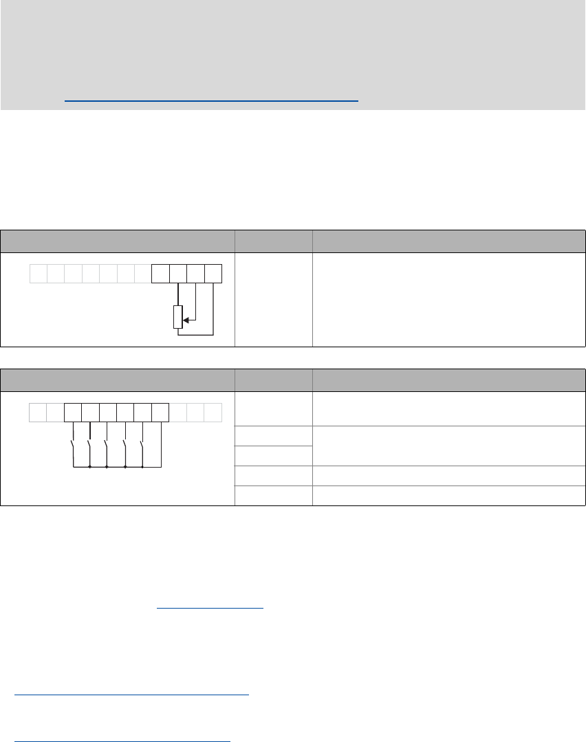
Digital inputs at X4 Terminal Function
DI1 ... DI4: All HIGH active
RFR Controller enable: HIGH level
Error reset: HIGH-LOW edge
DI1 Selection fixed setpoint 1 ... 3
DI2
DI3 Request DC-injection braking (DCB)
DI4 Request change of direction of rotation
DI1DI2
DI3
DI4
RFR
X4
24EDO1
12I
AR
A1U
GND
0 10V...
1k
10k
W
...
W
AR
A1U
GND
DI1DI2
DI3
RFR
X4
DO1 12I24E
DI4