
User guide

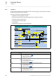


Table Of Contents
- Inverter Drives 8400 BaseLine C
- Overview of technical documentation for Inverter Drives 8400
- Contents
- 1 About this documentation
- 2 Introduction: Parameterising the controller
- 3 Commissioning
- 4 Device control (DCTRL)
- 5 Motor control (MCTRL)
- 5.1 Motor selection/Motor data
- 5.2 Selecting the control mode
- 5.3 Defining current and speed limits
- 5.4 V/f characteristic control (VFCplus)
- 5.5 Sensorless vector control (SLVC)
- 5.6 Parameterisable additional functions
- 5.7 Braking operation/braking energy management
- 5.8 Monitoring
- 6 I/O terminals
- 7 Drive application
- 8 Diagnostics & error management
- 9 System bus "CAN on board"
- 9.1 General information
- 9.2 LED status displays for the system bus
- 9.3 Going online via system bus (CAN on board)
- 9.4 Structure of the CAN data telegram
- 9.5 Communication phases/network management
- 9.6 Process data transfer
- 9.7 Parameter data transfer
- 9.8 Monitoring
- 9.9 Implemented CANopen objects
- 10 Parameter reference
- 10.1 Structure of the parameter descriptions
- 10.2 Parameter list
- C00002 | Device commands
- C00003 | Status of last device command
- C00006 | Motor control
- C00007 | Control mode
- C00010 | Minimum analog setpoint
- C00011 | Appl.: Reference speed
- C00012 | Acceleration time main setpoint
- C00013 | Deceleration time main setpoint
- C00015 | VFC: V/f base frequency
- C00016 | VFC: Vmin boost
- C00018 | Switching frequency
- C00019 | Auto DCB: Threshold
- C00021 | Slip comp.
- C00022 | Imax in motor mode
- C00023 | Imax in generator mode
- C00024 | Comparison value N_Act
- C00026 | AINx: Offset
- C00027 | AINx: Gain
- C00028 | AINx: Input voltage
- C00029 | AINx: Input current
- C00033 | AINx: Output value
- C00034 | AINx: Configuration
- C00036 | DCB: Current
- C00039 | Fixed setpoint x (L_NSet_1 n-Fix)
- C00050 | MCTRL: Speed setpoint
- C00051 | MCTRL: Actual speed value
- C00052 | Motor voltage
- C00053 | DC-bus voltage
- C00054 | Motor current
- C00056 | Torque
- C00057 | Maximum torque
- C00058 | Output frequency
- C00059 | Appl.: Reference frequency C11
- C00061 | Heatsink temperature
- C00064 | Device utilisation (Ixt)
- C00066 | Thermal motor load (I·xt)
- C00073 | Vp Imax controller
- C00074 | Ti Imax controller
- C00081 | Rated motor power
- C00084 | Motor stator resistance
- C00085 | Motor stator leakage inductance
- C00087 | Rated motor speed
- C00088 | Rated motor current
- C00089 | Rated motor frequency
- C00090 | Rated motor voltage
- C00091 | Motor cosine phi
- C00092 | Motor magnetising inductance
- C00093 | Power section identification
- C00094 | Password
- C00095 | Motor magnetising current
- C00097 | Rated motor torque
- C00098 | Device rated current
- C00099 | Firmware version
- C00100 | Firmware version
- C00105 | Deceleration time quick stop
- C00106 | Auto DCB: Hold time
- C00107 | DCB: Hold time
- C00114 | DIx inversion
- C00118 | DOx inversion
- C00120 | Motor overload threshold (I·xt)
- C00122 | Initial value motor overload (I·xt)
- C00123 | Device utilisation threshold (Ixt)
- C00134 | Ramp smoothing, main setpoint
- C00136 | Communication control words
- C00137 | Device state
- C00141 | Device settings
- C00142 | Auto-start option
- C00144 | Switching frequency reduction (temp.)
- C00150 | Status word
- C00155 | Status word 2
- C00158 | Cause for controller inhibit
- C00159 | Cause for quick stop QSP
- C00165 | Error information
- C00166 | Error information text
- C00168 | Error number
- C00169 | Time of error
- C00170 | Error counter
- C00173 | Mains voltage
- C00174 | Reduced brake chopper threshold
- C00177 | Switching cycles
- C00178 | Elapsed-hour meter
- C00179 | Power-on time meter
- C00182 | S-ramp time PT1
- C00200 | Firmware product type
- C00201 | Firmware compile date
- C00203 | Product type code
- C00222 | L_PCTRL_1: Vp
- C00223 | L_PCTRL_1: Tn
- C00224 | L_PCTRL_1: Kd
- C00225 | L_PCTRL_1: MaxLimit
- C00226 | L_PCTRL_1: MinLimit
- C00227 | L_PCTRL_1: Acceleration time
- C00228 | L_PCTRL_1: Deceleration time
- C00231 | L_PCTRL_1: Operating range
- C00234 | Oscillation damping influence
- C00242 | L_PCTRL_1: Operating mode
- C00243 | L_PCTRL_1: Acceleration time influence
- C00244 | L_PCTRL_1: Deceleration time influence
- C00245 | L_PCTRL_1: PID output value
- C00322 | Transmission mode CAN TxPDOs
- C00323 | Transmission mode CAN Rx PDOs
- C00324 | CAN transmit blocking time
- C00345 | CAN error status
- C00347 | CAN status HeartBeat producer
- C00350 | CAN node address
- C00351 | CAN baud rate
- C00352 | CAN Slave/Master
- C00353 | CAN IN/OUT COBID source
- C00354 | COBID
- C00355 | Active COBID
- C00356 | CAN time settings
- C00357 | CAN monitoring times
- C00359 | CAN status
- C00360 | CAN telegram counter
- C00364 | CAN MessageError
- C00366 | Number of CAN SDO channels
- C00367 | CAN Sync-Rx-Identifier
- C00368 | CAN Sync-Tx identifier
- C00369 | CAN Sync transmission cycle time
- C00372 | CAN_Tx_Rx_Error
- C00381 | CAN Heartbeat Producer Time
- C00385 | CAN NodeID Heartbeat producer
- C00386 | ConsumerTime HeartBeat Producer
- C00389 | PDO valid / invalid
- C00409 | LP_CanIn Mapping
- C00443 | DIx: Level
- C00444 | DOx: Level
- C00470 | LS_ParFree_b
- C00472 | LS_ParFree_a
- C00480 | LS_DisFree_b
- C00481 | LS_DisFree
- C00482 | LS_DisFree_a
- C00516 | Checksums
- C00517 | User menu
- C00565 | Resp. to mains phase failure
- C00574 | Resp. to brake resist. overtemp.
- C00581 | Resp. to LS_SetError_x
- C00592 | Resp. to CAN bus connection
- C00593 | Resp. to CANx_IN monitoring
- C00594 | Resp. to control word error
- C00598 | Resp. to open circuit AINx
- C00600 | Resp. to DC bus undervoltage
- C00601 | Del. resp.to fault: DC bus overvoltage
- C00604 | Resp. to device overload (Ixt)
- C00606 | Resp. to motor overload (I·xt)
- C00620 | 16-bit system connection
- C00621 | Bool system connection
- C00700 | LA_NCtrl: Analog connection list
- C00701 | LA_NCtrl: digital connection list
- C00725 | Current switching frequency
- C00727 | LS_Keypad: Digital values
- C00728 | LS_Keypad: Keypad analog values
- C00800 | L_MPot_1: Upper limit
- C00801 | L_MPot_1: Lower limit
- C00802 | L_MPot_1: Acceleration time
- C00803 | L_MPot_1: Deceleration time
- C00804 | L_MPot_1: Inactive fct.
- C00805 | L_MPot_1: Init fct.
- C00806 | L_MPot_1: Use
- C00830 | 16-bit analogue input
- C00831 | 16-bit common input
- C00833 | 8-bit input
- C00866 | CAN input words
- C00868 | CAN output words
- C00909 | Speed limitation
- C00910 | Frequency limitation
- C00990 | Flying restart fct.: Activation
- C00991 | Flying restart fct.: Process
- C00992 | Flying restart: Start frequency
- C00994 - Flying restart fct.: Current
- 10.2.1 Selection lists for configuration parameters
- 10.3 Table of attributes
- 11 Function library
- Index
- Your opinion is important to us
11 Function library
11.3 L_PCTRL_1
316
Lenze · 8400 BaseLine C · Reference manual · DMS 1.6 EN · 01/2014 · TD05
_ _ _ _ _ _ _ _ _ _ _ _ _ _ _ _ _ _ _ _ _ _ _ _ _ _ _ _ _ _ _ _ _ _ _ _ _ _ _ _ _ _ _ _ _ _ _ _ _ _ _ _ _ _ _ _ _ _ _ _ _ _ _ _
11.3.2 Ramp function generator
The PID output is led via a ramp function generator with linear characteristic. This serves to transfer
setpoint step-changes at the PID output into a ramp which should be as steep as possible.
[11-4] Acceleration and deceleration times
•t
ir
and t
if
are the desired times for changing between w1 and w2.
• The ramps for acceleration and deceleration can be set individually.
• C227
: Acceleration time T
ir
• C228
: Deceleration time T
if
•The t
ir
/t
if
values are converted into the required Ti times according to the following formula:
• The ramp function generator is immediately set to "0" by setting bInAct to TRUE.
11.3.3 Operating range of the PID process controller
The value range of the input signal nSet_a and thus the operating range of the PID process controller
can be limited with the following parameters:
• C231/1
: Pos. maximum (default setting: 199.9 %)
• C231/2
: Pos. minimum (default setting: 0.0 %)
• C231/3
: Neg. minimum (default setting: 0.0 %)
• C231/4
: Neg. maximum (default setting: 199.9 %)
11.3.4 Evaluation of the output signal
After the limitation, the output signal is evaluated with the influencing factor nInflu_a. The evalu-
ation is activated/suppressed along a ramp when the input bEnableInfluenceRamp is set to TRUE.
The ramp times are set with the parameters "Acceleration time influence" (C243
) and "Deceleration
time influence" (C244
).
w1, w2 = change of the main setpoint as a function of t
ir
and t
if
RFG-OUT = output of the ramp function generator
RFG-OUT
100 %
w2
w1
t
0%
t
ir
t
ir
T
ir
T
ir
T
ir
t
ir
100 %
w2 w1–
-----------------------
⋅=
T
if
t
if
100 %
w2 w1–
-----------------------
⋅=