
User guide


Table Of Contents
- Inverter Drives 8400 BaseLine C
- Overview of technical documentation for Inverter Drives 8400
- Contents
- 1 About this documentation
- 2 Introduction: Parameterising the controller
- 3 Commissioning
- 4 Device control (DCTRL)
- 5 Motor control (MCTRL)
- 5.1 Motor selection/Motor data
- 5.2 Selecting the control mode
- 5.3 Defining current and speed limits
- 5.4 V/f characteristic control (VFCplus)
- 5.5 Sensorless vector control (SLVC)
- 5.6 Parameterisable additional functions
- 5.7 Braking operation/braking energy management
- 5.8 Monitoring
- 6 I/O terminals
- 7 Drive application
- 8 Diagnostics & error management
- 9 System bus "CAN on board"
- 9.1 General information
- 9.2 LED status displays for the system bus
- 9.3 Going online via system bus (CAN on board)
- 9.4 Structure of the CAN data telegram
- 9.5 Communication phases/network management
- 9.6 Process data transfer
- 9.7 Parameter data transfer
- 9.8 Monitoring
- 9.9 Implemented CANopen objects
- 10 Parameter reference
- 10.1 Structure of the parameter descriptions
- 10.2 Parameter list
- C00002 | Device commands
- C00003 | Status of last device command
- C00006 | Motor control
- C00007 | Control mode
- C00010 | Minimum analog setpoint
- C00011 | Appl.: Reference speed
- C00012 | Acceleration time main setpoint
- C00013 | Deceleration time main setpoint
- C00015 | VFC: V/f base frequency
- C00016 | VFC: Vmin boost
- C00018 | Switching frequency
- C00019 | Auto DCB: Threshold
- C00021 | Slip comp.
- C00022 | Imax in motor mode
- C00023 | Imax in generator mode
- C00024 | Comparison value N_Act
- C00026 | AINx: Offset
- C00027 | AINx: Gain
- C00028 | AINx: Input voltage
- C00029 | AINx: Input current
- C00033 | AINx: Output value
- C00034 | AINx: Configuration
- C00036 | DCB: Current
- C00039 | Fixed setpoint x (L_NSet_1 n-Fix)
- C00050 | MCTRL: Speed setpoint
- C00051 | MCTRL: Actual speed value
- C00052 | Motor voltage
- C00053 | DC-bus voltage
- C00054 | Motor current
- C00056 | Torque
- C00057 | Maximum torque
- C00058 | Output frequency
- C00059 | Appl.: Reference frequency C11
- C00061 | Heatsink temperature
- C00064 | Device utilisation (Ixt)
- C00066 | Thermal motor load (I·xt)
- C00073 | Vp Imax controller
- C00074 | Ti Imax controller
- C00081 | Rated motor power
- C00084 | Motor stator resistance
- C00085 | Motor stator leakage inductance
- C00087 | Rated motor speed
- C00088 | Rated motor current
- C00089 | Rated motor frequency
- C00090 | Rated motor voltage
- C00091 | Motor cosine phi
- C00092 | Motor magnetising inductance
- C00093 | Power section identification
- C00094 | Password
- C00095 | Motor magnetising current
- C00097 | Rated motor torque
- C00098 | Device rated current
- C00099 | Firmware version
- C00100 | Firmware version
- C00105 | Deceleration time quick stop
- C00106 | Auto DCB: Hold time
- C00107 | DCB: Hold time
- C00114 | DIx inversion
- C00118 | DOx inversion
- C00120 | Motor overload threshold (I·xt)
- C00122 | Initial value motor overload (I·xt)
- C00123 | Device utilisation threshold (Ixt)
- C00134 | Ramp smoothing, main setpoint
- C00136 | Communication control words
- C00137 | Device state
- C00141 | Device settings
- C00142 | Auto-start option
- C00144 | Switching frequency reduction (temp.)
- C00150 | Status word
- C00155 | Status word 2
- C00158 | Cause for controller inhibit
- C00159 | Cause for quick stop QSP
- C00165 | Error information
- C00166 | Error information text
- C00168 | Error number
- C00169 | Time of error
- C00170 | Error counter
- C00173 | Mains voltage
- C00174 | Reduced brake chopper threshold
- C00177 | Switching cycles
- C00178 | Elapsed-hour meter
- C00179 | Power-on time meter
- C00182 | S-ramp time PT1
- C00200 | Firmware product type
- C00201 | Firmware compile date
- C00203 | Product type code
- C00222 | L_PCTRL_1: Vp
- C00223 | L_PCTRL_1: Tn
- C00224 | L_PCTRL_1: Kd
- C00225 | L_PCTRL_1: MaxLimit
- C00226 | L_PCTRL_1: MinLimit
- C00227 | L_PCTRL_1: Acceleration time
- C00228 | L_PCTRL_1: Deceleration time
- C00231 | L_PCTRL_1: Operating range
- C00234 | Oscillation damping influence
- C00242 | L_PCTRL_1: Operating mode
- C00243 | L_PCTRL_1: Acceleration time influence
- C00244 | L_PCTRL_1: Deceleration time influence
- C00245 | L_PCTRL_1: PID output value
- C00322 | Transmission mode CAN TxPDOs
- C00323 | Transmission mode CAN Rx PDOs
- C00324 | CAN transmit blocking time
- C00345 | CAN error status
- C00347 | CAN status HeartBeat producer
- C00350 | CAN node address
- C00351 | CAN baud rate
- C00352 | CAN Slave/Master
- C00353 | CAN IN/OUT COBID source
- C00354 | COBID
- C00355 | Active COBID
- C00356 | CAN time settings
- C00357 | CAN monitoring times
- C00359 | CAN status
- C00360 | CAN telegram counter
- C00364 | CAN MessageError
- C00366 | Number of CAN SDO channels
- C00367 | CAN Sync-Rx-Identifier
- C00368 | CAN Sync-Tx identifier
- C00369 | CAN Sync transmission cycle time
- C00372 | CAN_Tx_Rx_Error
- C00381 | CAN Heartbeat Producer Time
- C00385 | CAN NodeID Heartbeat producer
- C00386 | ConsumerTime HeartBeat Producer
- C00389 | PDO valid / invalid
- C00409 | LP_CanIn Mapping
- C00443 | DIx: Level
- C00444 | DOx: Level
- C00470 | LS_ParFree_b
- C00472 | LS_ParFree_a
- C00480 | LS_DisFree_b
- C00481 | LS_DisFree
- C00482 | LS_DisFree_a
- C00516 | Checksums
- C00517 | User menu
- C00565 | Resp. to mains phase failure
- C00574 | Resp. to brake resist. overtemp.
- C00581 | Resp. to LS_SetError_x
- C00592 | Resp. to CAN bus connection
- C00593 | Resp. to CANx_IN monitoring
- C00594 | Resp. to control word error
- C00598 | Resp. to open circuit AINx
- C00600 | Resp. to DC bus undervoltage
- C00601 | Del. resp.to fault: DC bus overvoltage
- C00604 | Resp. to device overload (Ixt)
- C00606 | Resp. to motor overload (I·xt)
- C00620 | 16-bit system connection
- C00621 | Bool system connection
- C00700 | LA_NCtrl: Analog connection list
- C00701 | LA_NCtrl: digital connection list
- C00725 | Current switching frequency
- C00727 | LS_Keypad: Digital values
- C00728 | LS_Keypad: Keypad analog values
- C00800 | L_MPot_1: Upper limit
- C00801 | L_MPot_1: Lower limit
- C00802 | L_MPot_1: Acceleration time
- C00803 | L_MPot_1: Deceleration time
- C00804 | L_MPot_1: Inactive fct.
- C00805 | L_MPot_1: Init fct.
- C00806 | L_MPot_1: Use
- C00830 | 16-bit analogue input
- C00831 | 16-bit common input
- C00833 | 8-bit input
- C00866 | CAN input words
- C00868 | CAN output words
- C00909 | Speed limitation
- C00910 | Frequency limitation
- C00990 | Flying restart fct.: Activation
- C00991 | Flying restart fct.: Process
- C00992 | Flying restart: Start frequency
- C00994 - Flying restart fct.: Current
- 10.2.1 Selection lists for configuration parameters
- 10.3 Table of attributes
- 11 Function library
- Index
- Your opinion is important to us
4 Device control (DCTRL)
4.2 Device states
56
Lenze · 8400 BaseLine C · Reference manual · DMS 1.6 EN · 01/2014 · TD05
_ _ _ _ _ _ _ _ _ _ _ _ _ _ _ _ _ _ _ _ _ _ _ _ _ _ _ _ _ _ _ _ _ _ _ _ _ _ _ _ _ _ _ _ _ _ _ _ _ _ _ _ _ _ _ _ _ _ _ _ _ _ _ _
4.2.2 MotorIdent
In the "MotorIdent" device state
• is the controller when being in the "SwitchedON
" state and having activated the "Identify motor
parameters" device command and being enabled.
• the application remains active.
• all system interfaces (IO, bus systems, etc.) remain active.
• error monitoring remains active
• the inverter is controlled independently of the setpoint sources.
After the motor parameter identification is completed, the state changes back to "SwitchedON
".
Tip!
Detailed information on motor parameter identification can be found in the "Automatic
motor data identification" subchapter on motor control. ( 70)
4.2.3 SafeTorqueOff
In the "SafeTorqueOff" device state
• the controller can only be if a safety module is connected and the power section is supplied and
at least one of the two safe inputs SI1/SI2 is set to LOW level.
• the next transaction to the "ReadyToSwitchON
" state takes place.
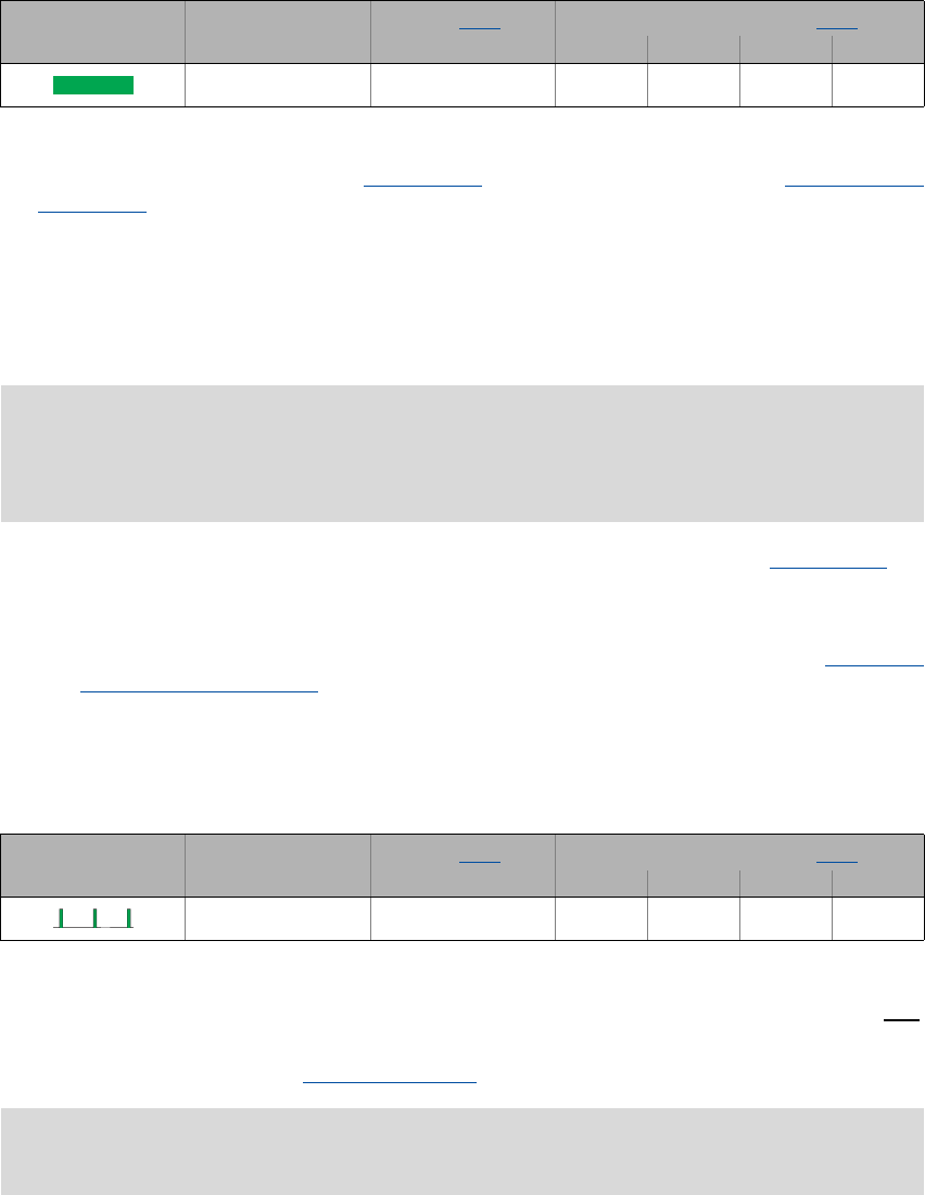
LED DRIVE READY LED DRIVE ERROR Display in C137 Display in status word 1 (C150)
Bit 11 Bit 10 Bit 9 Bit 8
OFF MotorIdent 0 0 1 0
Stop!
During motor parameter identification, the controller does not respond to setpoint
changes or control processes, (e.g. speed setpoints, quick stop, torque limitations).
LED DRIVE READY LED DRIVE ERROR Display in C137 Display in status word 1 (C150)
Bit 11 Bit 10 Bit 9 Bit 8
OFF SafeTorqueOff 1 0 1 0
Detailed and important information on the integrated safety system can be found in the
hardware manual!