
User Manual
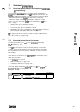
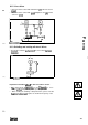
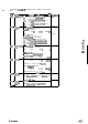

9.6 Selection
of the configoration
The setting of
CO05
determines which input channels and which
controls will be
activated:
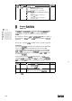
Configuration
1
Setpoint
1
=
1
Setpoint
2
=
/,
‘1
>
1
-201-
,,
_,,
_’
1
CO05
1 line
Speed
1
diameter
dancer
Signal
1
Terminals
718
(bipolar) or LECOM (bipolar)
or
1
Terminal
s
112
operating unit (bipolar)
.
Terminals
314
:
j”.
.,
1 (bipolar)
analog actual value
_,
I
-202-
,,
Master frequency X5
Terminals
1/2
Terminals 3/4
,jj’
:,I
(bipolar)
analog actual value
__
”
j_,,
,
”
“<_,
._,ji
,,
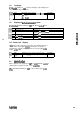
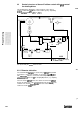
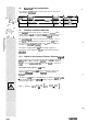
9.7
Diameter and radius detection
_,I’
:,
,:
~
The
diameter
is detected by means of ultrasonic
Sensors,
which
emit a distance
Signal
or a real radius
Signal.
Consequently, there
I
_‘_
..,
;
are different procedures to adapt the internal
Signal
processing.
The
encoder
Signal
is always provided via the terminals 1 and 2.
This
Signal
is converted with a resolution of 12 bits
plut
sign bit
(this corresponds
to
a
Signal
resolution of
+/-
4096; resulting in a
resolution of 1 OV/4096 = 2.44mV).
The input is equipped with a
filter
which largely suppresses
interference on the ultrasonic
Signal
when the field frequency is
calculated.
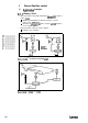
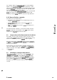
9.7.1
Signal of the ultrasonic Sensor: distance
Signal
For the adjustment of the radius detection when
using
an ultrasonic
Sensor,
which supplies a distance
Signal,
the sensor-axis distance
must
be entered
under
code
C180.
This value
must
be entered in
Volts.
Calculation of the value for
code
Cl 80:
For the calculation the bale
tan
have any diameter. (lt does not
make any
differente
whether the
minimum
or the maximum
diameter
is assumed.)
The value for
code
Cl80 is calculated from the distance
Signal
in
Volts
-
detected by the ultrasonic
Sensor
-
and the measures distance as
weil as the bale radius.
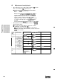
1
Actual value input
=
(
(a
+
0
Cl80 = Distance
Signal
7
=
Pl
a
L
rmmlr
+
I”“]
mm
1