
Owner manual


Appendix
Index table
10
l
139
KHB 13.0002−EN 4.1
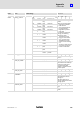
Characteristics
Possible settingsNameIndex
DescriptionSelectionLenze
6098
h
0 homing_method 17
−18 {1} 34
VAR INT8 RW
Value Direction Target Ref. point for zero
−18 Positive Limit
stop
Limit stop
Selection of the homing
variant.
There are 3 homing signals:
l Negative and positive
limit switches
l Zero pulse (periodic) of
the angle encoder
l Negative and positive
limit stops
If a method is selected for
homing, the following
settings are made:
l The reference source
(neg./pos. limit switch,
neg. / pos. limit stop)
l The direction and the
sequence of the homing
run
l The way in which the zero
pulse of the used angle
encoder is evaluated
−17 Negativ
e
Limit
stop
Limit stop
−2 Positive Limit
stop
Zero pulse
−1 Negativ
e
Limit
stop
Zero pulse
1 Negativ
e
Limit
switch
Zero pulse
2 Positive Limit
switch
Zero pulse
17 Negativ
e
Limit
switch
Limit switch
18 Positive Limit
switch
Limit switch
33 Negativ
e
Zero
pulse
Zero pulse
34 Positive Zero
pulse
Zero pulse
35 No
motion
Current actual
position
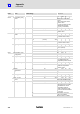
6099
h
0 homing_speeds
ARR UINT32 RO
Reading−out of the homing
speed
1 speed_during_
search_for_switch
100
0 {1 rpm} 2
32
−1
UINT32 RW MAP
Speed for approaching the
limit switch or the limit stop.
Usually the speed is then
changed and the final
position is approached with
a slower speed.
2 speed_during_
search_for_zero
10
0 {1 rpm} 2
32
−1
UINT32 RW MAP
Selection of the slower speed
609A
h
0 homing_
acceleration
250
0 {1 rpm/s} 2
32
−1
VAR UINT32 RW MAP
Selection of the acceleration
and deceleration for the
homing run.
The value applies to all
homing methods and to both
homing speeds.
60C0
h
0 interpolated_
submode_select
−2
−2 {} −2
VAR INT16 RW MAP
Selection of the interpolation
type.
−2 Linear interpolation without
buffer