
Owner manual

Device control
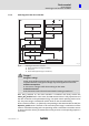
State diagram
State transitions of the drive controller
8
l
94
KHB 13.0002−EN 4.1
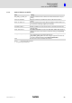
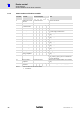
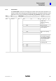
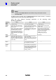
8.1.4 State transitions of the drive controller
Transition Command
Control word (bits)
Action
7 3 2 1 0
0 Switched on or reset
executed
Internal transition Execution of self−test.
1 Self−test successful Internal transition Activation of CAN communication.
2 Shut down and
controller enable
x x 1 1 0 None
3 Switch on x x 1 1 1 None
4 Enable operation x 1 1 1 1 On transition to the Operation_Enable state,
the power stage is switched on.
5 Disable operation x 0 1 1 1 Power stage is inhibited. Motor can be rotated
freely.
6 Shut down x x 1 1 0 Power stage is inhibited. Motor can be rotated
freely
7 Quick stop x x 0 1 x None
8 Shut down x x 1 1 0 Power stage is inhibited. Motor can be rotated
freely
9 Disable voltage x x x 0 x Power stage is inhibited. Motor can be rotated
freely.
10 Disable voltage x x x 0 x Power stage is inhibited. Motor can be rotated
freely.
11 Quick stop x x 0 1 x Braking is initiated.
12 Disable voltage or
braking completed
x x x 0 x Power stage is inhibited. Motor can be rotated
freely.
13 Error occurred Internal transition For non−critical errors response according to
fault_reaction_option_code. For critical errors
transition 14 follows.
14 Error handling is
completed
Internal transition Power stage is inhibited. Motor can be rotated
freely.
15 Fault reset and error
eliminated
0−>1 x x x x Error acknowledgement (at rising edge).
Tab. 13 State transitions of the drive controller
x not relevant