
Owner manual

Device control
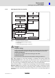
State diagram
Controller state
8
l
98
KHB 13.0002−EN 4.1
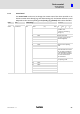
8.1.6 Controller state
Similar to the combination of several control word bits initiating different state changes,
the combination of different status word bits can be used to read out the current state of
the drive controller.
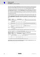
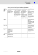
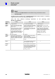
The below table lists the possible states of the state diagram and the corresponding bit
combinations indicating these states in the status word.
State Bit 6 Bit 5 Bit 3 Bit 2 Bit 1 Bit 0 Mask Value
0040
h
0020
h
0008
h
0004
h
0002
h
0001
h
Not_Ready_To_Switch_On 0 x 0 0 0 0 004F
h
0000
h
Switch_On_Disabled 1 x 0 0 0 0 004F
h
0040
h
Ready_to_Switch_On 0 1 0 0 0 1 006F
h
0021
h
Switched_On 0 1 0 0 1 1 006F
h
0023
h
Operation_Enable 0 1 0 1 1 1 006F
h
0027
h
Fault 0 x 1 1 1 1 004F
h
000F
h
Fault_Reaction_Active 0 x 1 1 1 1 004F
h
000F
h
Quick_Stop_Active 0 0 0 1 1 1 006F
h
0007
h
Tab. 15 Controller state
x not relevant
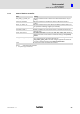
Example:
The above example shows which bits are to be set in the control word to enable the drive
controller. Now the new state is to be read out from the status word:
Transition from Switch_On_Disabled to Operation_Enable:
3. Write state transition 2 into the control word.
4. Wait until the Ready_To_Switch_On state is indicated in the status word.
Transition 2: Control word = 0006
h
, wait until (status word + 006F
h
) = 0021
h
is
indicated
1)
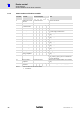
5. State transitions 3 and 4 can be summarised and written to the control word
together.
6. Wait until the Operation_Enable state is indicated in the status word.
Transitions 3 and 4: Control word = 000F
h
, wait until (status word + 006F
h
) = 0027
h
is
indicated
1)
The example is based on the assumption that no other bits are set in the control word
(since only bits 0 ... 3 are important for the transitions).
1) For the identification of the states, the bits not set have to be evaluated as well (see table). Therefore the status
word must be masked appropriately.