c300 .Oö% Ä.Oö%ä Controller c300 C30GAC...
Please read these instructions before you start working! Follow the enclosed safety instructions. Tip! Information and tools concerning the Lenze products can be found in the download area under www.lenze.
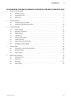
Contents 1 2 3 4 5 i About this documentation . . . . . . . . . . . . . . . . . . . . . . . . . . . . . . . . . . . . . . . . . . . . . . . . . . . . . . . 5 1.1 Document history . . . . . . . . . . . . . . . . . . . . . . . . . . . . . . . . . . . . . . . . . . . . . . . . . . . . . . 5 1.2 Conventions used . . . . . . . . . . . . . . . . . . . . . . . . . . . . . . . . . . . . . . . . . . . . . . . . . . . . . . 5 1.3 Notes used . . . . . . . . . . . . . . . . . . . . . . . . . . . . . . .
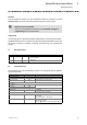
i 6 7 8 4 Contents Electrical installation . . . . . . . . . . . . . . . . . . . . . . . . . . . . . . . . . . . . . . . . . . . . . . . . . . . . . . . . . . . . 25 6.1 Important notes . . . . . . . . . . . . . . . . . . . . . . . . . . . . . . . . . . . . . . . . . . . . . . . . . . . . . . . . 25 6.2 EMC−compliant wiring . . . . . . . . . . . . . . . . . . . . . . . . . . . . . . . . . . . . . . . . . . . . . . . . . . 26 6.3 Connecting voltage supply (24 V) . . . . . . . . . . . . . . . .
About this documentation 1 Document history 0Fig. 0Tab. 0 1 About this documentation Contents This documentation provides you with information about the intended use of the controller c300 in the Lenze "Controller−based Automation" control system. Reference manual "Controller" Here you can find detailed information on the parameter setting and programming of the Lenze Controllers. Target group This documentation is directed at qualified skilled personnel according to IEC 60364.
1 About this documentation Notes used 1.
Safety instructions 2 General safety information 2 Safety instructions 2.1 General safety information Scope The following general safety instructions apply to all Lenze drive and automation components. The product−specific safety and application notes given in this documentation must be observed! For your own safety Danger! Disregarding the following basic safety measures may lead to severe personal injury and damage to material assets! ¯ Lenze drive and automation components ... ...
2 Safety instructions General safety information Mechanical installation ¯ Install the product according to the regulations of the corresponding documentation. In particular observe the section "Operating conditions" in the chapter "Technical data". ¯ Provide for a careful handling and avoid mechanical overload. During handling neither bend components, nor change the insulation distances.
Safety instructions 2 General safety information Disposal ¯ Recycle or dispose of the product according to the applicable regulations. Lenze ¯ BA_c300 ¯ 2.
2 Safety instructions Product−specific safety instructions 2.2 Product−specific safety instructions ¯ The device is classified as a class A device and can cause radio interference in residential areas. In this case, the operator may have to take special measures. Any costs arising from these measures have to be paid by the operator. ¯ In the event of an error, the device must be switched to a deenergised state immediately. For this, unplug the supply connector.
Product description 3 Scope of supply 3 Product description EPM-S701 Controller I/O System 1000 c300_005 Fig. 3−1 Controller c300 (grey: connected I/O system 1000) System manual "I/O system 1000" Here you can find detailed information on the I/O system 1000. 3.
3 Product description Application as directed 3.2 Application as directed The Controller is used as directed if it is solely used for implementing control and operating concepts or for presenting information in usual industrial and commercial fields. A different use, or one beyond these purposes, is not permissible.
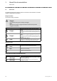
Product description 3 Device features 3.3 Device features Field Type/ mounting Processor type Fanless Controller c300 ¯ Mounting on standard DIN rail (35 mm) ¯ I/O system 1000 can be connected via internal backplane bus Memory RAM Read−only memory (flash) SD/SDHC card Retain memory Interfaces SD/SDHC card Ethernet EtherCAT 1) CANopen 2) USB 2.
3 Product description Identification 3.4 Identification How to find information c300_002 Pos. 1 2 3 4 Description Nameplate Windowsâ licence number (can also be attached on the right side) Type designation Technical data Nameplate Type: Input: HW: SW: 32xxC_002 Fig. 3−2 Pos.
Product description 3 Identification Type code Type code Controller c300 C30GAC00000F3G x XXX−02S3C x 00 000 Extensions 0 = without Control technology runtime software 3 = Logic: LPC1000 (V3.x) Lenze ¯ BA_c300 ¯ 2.
3 Product description Controls and displays 3.5 Controls and displays Fig. 3−3 Control and display elements c300_001 Pos.
Product description 3 UPS functionality 3.6 UPS functionality With the UPS functionality (uninterruptible power system), the device is provided with a backup function. This means that, in the case of a supply voltage failure, the user data (retain variables, logbook data) are saved before the device is switched off.
4 Technical data General data and operating conditions 4 Technical data 4.
Technical data 4 Mechanical data Operating conditions Ambient conditions Climatic Storage/transport Operation Air humidity Pollution Mechanical Vibration Shock Site altitude Operation EN 60721−3−2 EN 60721−3−2 EN 60721−3−3 EN 61131−2 2K3: −25 ... +70 °C 3K3: Horizontal mounting: 0 ... +55 °C Vertical mounting: 0 ... +55 °C 3K3 (without condensation, relative humidity 10 ...
5 Mechanical installation Important notes 5 Mechanical installation 5.1 Important notes ¯ The mounting site must always comply with the operating conditions stated in the technical data. Take additional measures if necessary. ¯ The mechanical connections must always be ensured. ¯ The mounting rail and the mounting plate in the control cabinet must be electrically conductive and free of lacquer.
Mechanical installation 5 Dimensions Dimensions mm 2 10 100 mm 35 mm 127 mm 42 150 mm 5.2 mm c300_001m Fig. 5−1 32xxC_003 Dimensions and mounting clearances Lenze ¯ BA_c300 ¯ 2.
5 Mechanical installation Mounting 5.3 Mounting Stop! Short circuit on the backplane bus contact The backplane bus signals are forwarded to the adjacent I/O system module via a contact strip. If current−carrying material touches this contact strip, a short circuit may occur. Furthermore there is the danger of static discharge if the contact strip is touched. Possible consequences: ¯ Destruction of the controller and/or the I/O system module.
Mechanical installation 5 Mounting Mounting the I/O system 1000 c300 c300 1 2 0 EPM-S701 , EDKPM-SXXX 3 0 I/O System 1000 0 c300_008 Fig. 5−3 Mounting How to mount the I/O system 1000: 1. Remove cover (A) from controller. 2. Attach I/O system modules to the DIN rail directly next to the controller. 3. Attach cover (A) to the side contacts of the outermost I/O system module. Lenze ¯ BA_c300 ¯ 2.
5 Mechanical installation Dismounting 5.4 Dismounting 1 2 OFF 3 c300_007 Fig. 5−4 Disassembly How to remove the Controller: 1. Switch off the supply voltage. 2. Loosen the locking lever for the DIN rail. 3. Remove the Controller from the DIN rail. 24 Lenze ¯ BA_c300 ¯ 2.
Electrical installation 6 Important notes 6 Electrical installation 6.1 Important notes The installation must be carried out by qualified, skilled personnel familiar with the applicable national standards. Stop! Short circuit and static discharge The device contains components which are endangered in the case of short circuit or static discharge. Possible consequences: ¯ The device or parts of it will be destroyed.
6 Electrical installation EMC−compliant wiring 6.2 EMC−compliant wiring Notes on EMC−compliant wiring General notes ¯ The electromagnetic compatibility of the system depends on the type of installation and care taken. Especially consider the following: – Structure – Shielding – Earthing ¯ For installations differing from the one described, the evaluation of the conformity with the EMC Directive requires a check of the system regarding the EMC limit values.
Electrical installation 6 Connecting voltage supply (24 V) Connection plan 6.3 Connecting voltage supply (24 V) Stop! No device protection against excessive input voltage The voltage input is not fused internally. Possible consequences: ¯ The device can be destroyed when the input voltage is too high. Protective measures: ¯ Observe the max. permissible input voltage. ¯ Professionally fuse the device on the input side against voltage fluctuations and voltage peaks.
6 Electrical installation Interfaces for peripheral devices Ethernet interface 6.4 Interfaces for peripheral devices 6.4.1 Ethernet interface Figure Connection X3: Ethernet LAN Connection type RJ45 socket IPC001 Cable type Network cable CAT5e S/FTP (recommended) Cable length max. 100 m Note! If the RJ45 plug connection is exposed to oscillating or vibrating stress: ¯ Use a strain relief in the immediate vicinity of the RJ45 socket.
Electrical installation 6 Interfaces for peripheral devices CAN port 6.4.3 CAN port Figure EL100−011 Connection Connection type Cable type X5: CAN bus connection Pin 1: CAN−GND (CG) Pin 2: CAN−LOW (LO) Pin 3: not assigned Pin 4: CAN−HIGH (HI) Pin 5: not assigned 5−pole Phoenix Combicon socket CAN cable complying with ISO 11898−2 with Phoenix Combicon plug, MSTB 2.5 / 5−STF−5.
6 Electrical installation Interfaces for peripheral devices Cable fixing and strain relief 6.4.4 Cable fixing and strain relief Fasten the cable bundles to the device using cable ties. The fastening points for cable ties for strain relief are located at the top and at the bottom of the device, respectively. c300_022 EL100−034 Fig. 6−4 Cable retention and strain relief 6.4.5 USB interface Figure Connection IPC001 30 X4: USB 2.0 connection (max.
Electrical installation 6 Interfaces for peripheral devices SD card interface 6.4.6 SD card interface Figure Connection SD/SDHC card Connection type Slot Cable type − Note! The combination of control technology software and application data on the SD card ensures that the data suit the respective application in the present version. This enables an easy transfer of the SD card to another device.
7 Maintenance Regular checks 7 Maintenance 7.1 Regular checks The system is maintenance−free. Nevertheless, visual inspections must be carried out at regular intervals which must not be too long, depending on the ambient conditions. Please check the following: ¯ Does the environment of the system still meet the operating conditions specified in the Technical data? ¯ Is the heat dissipation impeded by dust or dirt? ¯ Are the mechanical and electrical connections still okay? 7.
Index 8 8 Index 0 ...
8 Index M O Mains connection (24 V), 27 Operating conditions, 19 Maintenance, 32 Operating temperature, 19 − Cleaning, 32 − Regular checks, 32 Overview of the control/display elements, 16 Mechanical installation, 20 − Dimensions and mounting clearances, 21 − Important notes, 20 Mounting, 22 − Important notes, 20 Mounting clearances, 21 Mounting conditions, 19 Mounting place, 19 Mounting position, 19 Mounting the controller, 22 Mounting the I/O system 1000, 23 Mounting type, 19 Shock resistance,
© 08/2014 | BA_c300 | .Oö% | 2.0 | TD17 Lenze Automation GmbH Postfach 10 13 52, D−31763 Hameln Hans−Lenze−Str. 1, D−31855 Aerzen Germany +49 5154 82−0 +49 5154 82−2800 lenze@lenze.com www.lenze.com Lenze Service GmbH Breslauer Straße 3, D−32699 Extertal Germany 008000 2446877 (24 h helpline) +49 5154 82−1112 service@lenze.