
Instructions Owner's manual


Electrical installation
Connecting voltage supply (24 V)
Connection plan
6
27
Lenze ¯ BA_c300 ¯ 2.0
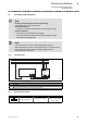
6.3 Connecting voltage supply (24 V)
Stop!
No device protection against excessive input voltage
The voltage input is not fused internally.
Possible consequences:
¯ The device can be destroyed when the input voltage is too high.
Protective measures:
¯ Observe the max. permissible input voltage.
¯ Professionally fuse the device on the input side against voltage
fluctuations and voltage peaks.
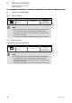
Note!
The controller starts as soon as the supply voltage is applied.
After the operating system has been shut down, the controller switches
off automatically. For restarting, the supply voltage has to be
disconnected for a short time.
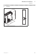
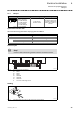
6.3.1 Connection plan
L1
N
PE
L1
N
+
0V
+24
+
~=
0V
PE +24 V
+
0
1
F
2
CPC2xx−006
Fig. 6−1 Connection plan for voltage supply (24 V)
Pos. Description
A
Controller
B Power supply unit
C
PE conductor connection on the supply side via DIN rail
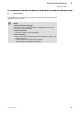
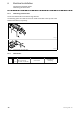
6.3.2 Mains connection (24 V)
Figure Connection Connection type Cable type
0V U
X1:
DC voltage supply (24 V)
3−pin Combicon socket
Cable with Combicon plug
(conductor cross−section
max. 2.5 mm
2
)
IPC001