Automation Systems Controller-based Automation 13462732 Ä.
Contents ________________________________________________________________ 1 1.1 1.2 1.3 1.
Contents ________________________________________________________________ 5 Commissioning _ _ _ _ _ _ _ _ _ _ _ _ _ _ _ _ _ _ _ _ _ _ _ _ _ _ _ _ _ _ _ _ _ _ _ _ _ _ _ _ _ _ _ _ _ 50 6 6.1 6.2 6.3 6.4 6.5 6.6 6.
1 About this documentation ________________________________________________________________ 1 About this documentation This system manual contains some information relating to the system structure ... • of the controller-based visualisation technology (control technology release 3.x), and • of the PC-based visualisation technology (control technology release 2.x). As a higher-level system manual, the document provides an overview of the visualisation technology's system components and their interaction.
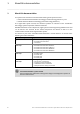
1 About this documentation ________________________________________________________________ More technical documentation for Lenze components Further information on Lenze products which can be used in conjunction with Controller-based Automation can be found in the following sets of documentation: Mounting & wiring Symbols: Mounting instructions • Controller • Communication cards (MC-xxx) • I/O system 1000 (EPM-Sxxx) • Inverter, Servo Drives • Communication modules Printed documentation Online h
1 About this documentation 1.1 Document history ________________________________________________________________ 1.1 Document history Version 6 Description 1.0 10/2009 TD11 First edition 1.1 08/2010 TD11 Update for the "Controller-based Automation" 3.x Lenze automation system • Lenze Controller 3200 C supplemented. 1.2 02/2011 TD11 Update for the "PC-based Automation" 2.5 Lenze automation system • Industrial PC x800 supplemented. 1.
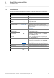
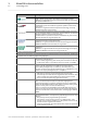
1 About this documentation 1.2 Conventions used ________________________________________________________________ 1.2 Conventions used This documentation uses the following conventions to highlight different types of information: Type of information Writing Examples/notes Spelling of numbers Decimal Decimal separator Hexadecimal Binary • Nibble Normal spelling Point 0x[0 ... 9, A ... F] 0b[0, 1] Example: 1234 The decimal point is always used. For example: 1234.
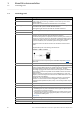
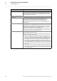
1 About this documentation 1.3 Terminology used ________________________________________________________________ 1.3 Terminology used Term Meaning Controller The Industrial PC (IPC) or controller is the central component of the automation system which controls the Logic and Motion functionalities by means of the runtime software. The controller communicates with the field devices via the fieldbus.
1 About this documentation 1.3 Terminology used ________________________________________________________________ Term Meaning CANopen® is a communication protocol based on CAN. The Lenze system bus (CAN on board) operates with a subset of this communication protocol. CANopen® is a registered community trademark of the CAN user organisation CiA® (CAN in Automation e. V.).
1 About this documentation 1.3 Terminology used ________________________________________________________________ Term Meaning ST ST allows a more structured programming than IL and therefore replaces IL more and more. Many software developers continue programming with IL because of the increased memory requirements of the ST programs (after compilation). When using smaller PLCs, the memory limits will be reached sooner in the event of increased memory requirements.
1 About this documentation 1.4 Definition of the notes used ________________________________________________________________ 1.
2 Safety instructions ________________________________________________________________ 2 Safety instructions Please observe the following safety instructions when you want to commission an inverter or system using the Industrial PC.
3 Controller-based Automation: Central motion control ________________________________________________________________ 3 Controller-based Automation: Central motion control The Lenze automation system "Controller-based Automation" serves to create complex automation solutions with central motion control. Here, the controller is the control centre of the system.
3 Controller-based Automation: Central motion control ________________________________________________________________ Lenze provides especially coordinated system components: • Engineering software The Lenze Engineering tools on your Engineering PC (Windows® operating system) serve to parameterise, configure, and diagnose the system. The Engineering PC communicates with the controller via Ethernet.
4 System description 4.1 Visualisation system structure ________________________________________________________________ 4 System description This chapter describes the use of an Industrial PC as a visualisation device and the required components. 4.1 Visualisation system structure The field of visualisation technology distinguishes between three system architectures.
4 System description 4.1 Visualisation system structure ________________________________________________________________ 4.1.1 Stand-alone application The control system (controller) and visualisation (Visu) run on separate controllers, respectively. • The visualisation IPC (Visu IPC) directly communicates with an external control system and the lower-level field devices. A fieldbus or a higher-level Ethernet network are used for communication.
4 System description 4.1 Visualisation system structure ________________________________________________________________ 4.1.2 Integrated control system Note! The integrated control system is only provided for IPCs/controllers with an integrated monitor panel or for IPCs/controllers with a DVI interface for an external monitor panel/ display. The control system (Logic/Motion) and the visualisation run on the same IPC (controller, Visu). The visualisation (Visu) ...
4 System description 4.1 Visualisation system structure ________________________________________________________________ 4.1.3 Client/server system The client/server system is a classical SCADA application (Supervisory Control and Data Acquisition). • A central server, IPC (controller) for data management (alarm, recipe, trend management) is typical of this application. • Operation and monitoring of the machine/system can be carried out via an optional number of client devices.
4 System description 4.2 System components ________________________________________________________________ 4.2 System components 4.2.1 Controller: "Controller-based Automation" (control technology version 3.x) Lenze offers a range of different controllers in cabinet and panel design. Depending on the application, the controllers are provided with different processors, panel sizes, and runtime modes. 4.2.
4 System description 4.2 System components ________________________________________________________________ 4.2.3 Runtime software The Industrial PC is the core of the visualisation system. To perform the tasks required, the Industrial PC requires the so-called "runtime software". The runtime software for instance comprises the operating system (Windows® CE).
4 System description 4.2 System components ________________________________________________________________ 4.2.3.2 "Visu" runtime software All visualisation applications are executed within a runtime environment (runtime). The licence required for this purpose depends on the hardware operating system. The "Visu" runtime software is not pre-installed on the Lenze Industrial PCs, but is loaded to the IPC together with the visualisation application.
4 System description 4.2 System components ________________________________________________________________ »VisiWinNET®« Compact CE This runtime system for Windows® CE systems only requires a small amount of memory space and is specially designed for systems with a lower processor power. Typical scopes of application are the machine-oriented operation and monitoring with low demands with regard to the visualisation. They are used in stand-alone applications and integrated control systems.
4 System description 4.2 System components ________________________________________________________________ »VisiWinNET®« Standard Client/Server (C/S) This runtime system for Windows® XP as client/server system offers the whole functional range of the »VisiWinNET®« standard. However, all information used commonly is managed centrally on one server. So-called "Terminal Clients" serve as clients.
4 System description 4.
4 System description 4.2 System components ________________________________________________________________ 4.2.3.3 "Visu" runtime software - licence information A licence is required for executing the "Visu" runtime software. The licence information indicates which runtime software version (Compact, Standard, etc.) may be used, how many clients are allowed to log on to a client/server system, and how many variables (power tags) can be displayed via the visualisation.
4 System description 4.2 System components ________________________________________________________________ 4.2.
4 System description 4.2 System components ________________________________________________________________ 4.2.4.1 Direct access to the field devices • The controller and the IPC (Visu) access the fieldbus independently of each other. • The visualisation (Visu) can access the parameters of the field devices and the parameters of the controller.
4 System description 4.2 System components ________________________________________________________________ 4.2.4.2 Access to the control system and the field devices connected • When using the Lenze control technology, the visualisation can directly access the field devices without any further impact, using the Industrial PC as gateway. When different control systems are used, this is usually not possible. Therefore it is recommended to only use data of the controller.
4 System description 4.2 System components ________________________________________________________________ 4.2.5 Engineering tool»VisiWinNET®« With »VisiWinNET®«, Lenze provides a scalable Engineering tool to create visualisation applications according to individual requirements and load them on the Industrial PCs. »VisiWinNET®« is provided in the versions »VisiWinNET®« Smart and »VisiWinNET®« Professional. 4.2.5.
4 System description 4.2 System components ________________________________________________________________ 4.2.5.2 »VisiWinNET®« Professional »VisiWinNET®« Professional is completely integrated into the Microsoft® Visual Studio .NET integrated development environment and provides the basis for the creation of visualisation and SCADA applications with a high functionality. The ready-made templates and modules can be used to smoothly create applications via "drag and drop".
4 System description 4.2 System components ________________________________________________________________ 4.2.6 Backup of visualisation data (UPS functionality) The Controllers 3221 C/3231 C back up the visualisation data cyclically every 60 seconds. The visualisation data backed up are therefore not exactly up-to-date after a voltage failure.
4 System description 4.3 Network topologies ________________________________________________________________ 4.3 Network topologies The Lenze visualisation system supports different control and bus systems connected via »VisiWinNET®« channels. Depending on the control or bus system used, the communication and network options are different. Communication has an impact on the usability of the operating systems and device lines. 4.3.
4 System description 4.3 Network topologies ________________________________________________________________ Direct drivers... • are contained in the scope of supply of the »VisiWinNET®« development packages. • are transferred from the Engineering PC to the Industrial PC when the visualisation application is downloaded. • are specially tailored to »VisiWinNET®« and can only be used for this software program. OPC servers... • can be universally used and offer an open interface.
4 System description 4.3 Network topologies ________________________________________________________________ 4.3.2 Browsing variables For defining the variables to be displayed, »VisiWinNET®« allows you to "browse" variables. Depending on the bus system and the control system type, there are different file formats available from which »VisiWinNET®« can take the variable information and offer it for selection.
4 System description 4.3 Network topologies ________________________________________________________________ 4.3.3 EtherCAT® Note! For Industrial PCs of the EL 1xx, EL x8xx, CS x8xx, and CPC x8xx series in control technology release 2.5, the EtherCAT bus system is not provided. The EtherCAT bus system only allows one single master.
4 System description 4.3 Network topologies ________________________________________________________________ Available runtime software for Lenze controllers Controller 3231 C 3241 C p300 p500 Runtime Software Windows® Compact CE Logic Motion Visu Access Driver type Driver name Communication type Field devices OPC Lenze.Digitec.OPCTunnel.
4 System description 4.3 Network topologies ________________________________________________________________ 4.3.4 CANopen® Note! • Due to the access mechanisms of the CAN bus, the real-time capability of the bus may be influenced by the visualisation if visualisation and control system communicate independently of each other with the field devices via CAN. Therefore, this constellation is only with restrictions suitable for the use in Motion systems.
4 System description 4.3 Network topologies ________________________________________________________________ Functions • Direct access to field devices via CANopen. Access to the control system and the field devices connected ( 28) • Control system access via CAN if the control systems have an SDO object directory. • Control system access via Ethernet if an OPC server is available. • SDO and PDO access (only with direct drivers). • Visualisation variables can be imported from EDS/DCF/GDC files.
4 System description 4.3 Network topologies ________________________________________________________________ Overview of the communication drivers and browsers available Device series Controller 3231 C 3241 C p300 p500 Runtime Software Windows® CE Logic Motion Visu Access Driver type Driver name Communication type Field devices OPC Lenze.Digitec.OPCTunnel.DA 1) CAN OPC tunnel Lenze.OPC_CANbus_CE 1) PLC variables (Logic & Motion) OPC Lenze.Digitec.OPCTunnel.DA 1) CoDeSys.OPC.
4 System description 4.3 Network topologies ________________________________________________________________ 4.3.5 PROFIBUS® Visualisation applications with PROFIBUS are available for the following Lenze devices: • HMI series EL 100 • Industrial PCs: EL 1800-9800, CS 5800-9800 and CPC 2800 The Industrial PCs use an OPC server for communication.
4 System description 4.3 Network topologies ________________________________________________________________ Note! The data of the connected PROFIBUS slaves cannot be directly accessed! As an alternative, the control system can access variables of the field devices. The control system automatically reads in the variables and provides them to the visualisation in a transfer area.
4 System description 4.
4 System description 4.3 Network topologies ________________________________________________________________ 4.3.6 PROFINET® Visualisation applications with PROFINET are available for the following Lenze devices: • HMI series EL 100 • Industrial PCs: EL 1800-9800, CS 5800-9800 and CPC 2800 The Industrial PCs use an OPC server for communication.
4 System description 4.3 Network topologies ________________________________________________________________ Functions • Access to Siemens S7-300/400 control systems via PROFIBUS (MPI) • Access to VIPA control systems via PROFINET (RFC1006) • Visualisation variables can be imported from STEP7® Note! The data of the PROFINET field devices connected cannot be accessed directly! As an alternative, the variables of the field devices should be accessed via the control system.
4 System description 4.
4 System description 4.3 Network topologies ________________________________________________________________ 4.3.7 Ethernet Most control systems are equipped with an integrated Ethernet connection. Since Ethernet is much more powerful than most fieldbuses, it is recommended to access the control system via Ethernet (and not via the lower-level fieldbus system). This option has been described in the previous bus-specific chapters.
4 System description 4.
4 System description 4.
4 System description 4.3 Network topologies ________________________________________________________________ 4.3.8 Further bus systems In addition to access via own direct drivers, »VisiWinNET®« also allows you to access field devices via standardised OPC servers. If a standardised OPC server is available, any devices can be integrated in »VisiWinNET®«.
5 Commissioning ________________________________________________________________ 5 Commissioning For commissioning the visualisation system you need an Engineering PC. This can be a standard laptop. The programs required for configuring, parameterising, and commissioning the visualisation system are installed on the Engineering PC.
6 Remote maintenance and diagnostics 6.1 Remote maintenance with an external router ________________________________________________________________ 6 Remote maintenance and diagnostics For a remote maintenance of a Controller, the standard mechanisms for remote maintenance of a PC can be used. The standard mechanisms ...
6 Remote maintenance and diagnostics 6.2 Remote maintenance with a separate remote PC ________________________________________________________________ 6.2 Remote maintenance with a separate remote PC [6-1] Note! Setting a remote maintenance may endanger the IT safety! • This is particularly relevant if the remote PC is connected to an Ethernet network. • Contact your IT administrator to take the necessary safety measures.
6 Remote maintenance and diagnostics 6.3 Log-in on an IPC of the x800 device series (PC-based automation) ________________________________________________________________ 6.3 Log-in on an IPC of the x800 device series (PC-based automation) An RAS server runs on the IPCs. A user can log-in via modem/ISDN card on this RAS server. If someone dials-in from a remote maintenance PC via this medium, the IPC executes a password check and then activates the connection. 6.
6 Remote maintenance and diagnostics 6.5 File transfer via FTP ________________________________________________________________ 6.5 File transfer via FTP The File Transfer Protocol (FTP) is a network protocol for the transfer of data within networks. • FTP makes it possible to exchange files between the Lenze controller, IPC, or HMI and other PCs. • The controller, IPC, or HMI data can be accessed via FTP connection. • FTP requires an existing connection or a remote connection.
6 Remote maintenance and diagnostics 6.6 Web server/»WebConfig« ________________________________________________________________ 6.6 Web server/»WebConfig« The Lenze controllers, IPCs, and HMIs are provided with an integrated web server. The web server makes it possible to parameterise the devices via »WebConfig«. • The controller, IPC, and HMI parameters can be displayed/altered via web browser.
6 Remote maintenance and diagnostics 6.7 »Virtual Network Computing (VNC)«: Redirecting screen contents/entries ________________________________________________________________ 6.7 »Virtual Network Computing (VNC)«: Redirecting screen contents/entries For remote maintenance of a Lenze controller, IPC, and HMI, the screen contents can be redirected to the Engineering PC. This makes it possible to view all keyboard entries/mouse movements of the local PC on the remote PC.
7 Appendix 7.1 Information regarding the FDA conformance ________________________________________________________________ 7 Appendix 7.1 Information regarding the FDA conformance »VisiWinNET®« can provide a visualisation that complies with FDA regulations 21 CFR part 11 of the Food and Drug Administration. These regulations are applicable to machines exported into the U.S..
8 Glossary ________________________________________________________________ 8 Glossary A Application Implementation of a concrete function (e.g. speed control) on an individual device. Application Samples Predefined application samples/sample projects for commissioning Lenze inverters. Application templates Lenze application template for creating standardised modular applications in the »PLC Designer«. Bus server Fieldbus-specific OPC server according to DRIVECOM specification.
8 Glossary ________________________________________________________________ D DCOM Abbreviation for "Distributed Component Object Model": COM where the executable objects are distributed to different computers within one local area network. COM DRIVECOM "DRIVECOM User Group e.V.": International association of manufacturers for drive technology, universities and institutes with the objective of developing a simple integration of drives into open automation structures. www.drivecom.
8 Glossary ________________________________________________________________ O Object-oriented programming (OOP) Object-oriented programming (OOP) is a procedure for structuring computer programs where data belonging together and the corresponding program logic are combined to objects (separate units).
Index ________________________________________________________________ A P Access to the control system and the field devices connected 28 Application notes 11 PC-based Automation 19 PROFIBUS 40 PROFINET 43 B Backing up visualisation data (UPS functionality) 31 Backup of visualisation data (UPS functionality) 31 Battery pack (ACCU-PACK) 31 Browsing online/offline 34 Browsing variables 34 C CANopen 37 Capacitor pack (CAPS-PACK) 31 Channels 32 Client/server system 18 Commissioning 50 Computer access via
)(('%$&. Your opinion is important to us These instructions were created to the best of our knowledge and belief to give you the best possible support for handling our product. Perhaps we have not succeeded in achieving this objective in every respect. If you have suggestions for improvement, please e-mail us to: feedback-docu@lenze.com Thank you very much for your support.
Controller-based Automation - Visualisation · System Manual · GHBPCBAUTVISU · 13462732 · DMS 1.5 EN · 04/2014 · TD17 Lenze Automation GmbH Postfach 10 13 52, D-31763 Hameln Hans-Lenze-Straße 1, D-31855 Aerzen Germany +49 5154 82-0 +49 5154 82-2800 lenze@lenze.com www.lenze.com Service Lenze Service GmbH Breslauer Straße 3, D-32699 Extertal Germany 008000 24 46877 (24 h helpline) +49 5154 82-1112 service@lenze.