Automation Systems Controller-based Automation 13461044 Ä.
Contents ________________________________________________________________ 1 1.1 1.2 1.3 1.
Contents ________________________________________________________________ 5 5.1 5.2 5.3 System architecture _ _ _ _ _ _ _ _ _ _ _ _ _ _ _ _ _ _ _ _ _ _ _ _ _ _ _ _ _ _ _ _ _ _ _ _ _ _ _ _ _ _ _ Communication link between Engineering PC and field devices _ _ _ _ _ _ _ _ _ _ _ _ _ _ _ _ _ _ _ Online connection via the gateway function of the controller via CAN/EtherCAT _ _ _ _ _ _ _ _ _ _ Direct connection _ _ _ _ _ _ _ _ _ _ _ _ _ _ _ _ _ _ _ _ _ _ _ _ _ _ _ _ _ _ _ _ _ _ _ _ _ _ _ _ _ _ _ _ 5.3.
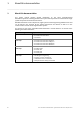
1 About this documentation ________________________________________________________________ 1 About this documentation This system manual contains general information on the Lenze "Controller-based Automation"system. As a starting document this system manual provides an overview of the single system components and their interconnection.
1 About this documentation ________________________________________________________________ More technical documentation for Lenze components Further information on Lenze products which can be used in conjunction with Controller-based Automation can be found in the following sets of documentation: Mounting & wiring Mounting instructions • Controller • Communication cards (MC-xxx) • I/O system 1000 (EPM-Sxxx) • Inverter, Servo Drives • Communication modules Symbols: Printed documentation Online he
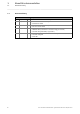
1 About this documentation 1.1 Document history ________________________________________________________________ 1.1 Document history Version 6 Description 1.0 08/2010 TD11 First edition for the Lenze automation system "Controller-based Automation" 3.x 1.1 11/2011 TD11 Update for the Lenze automation system "Controller-based Automation" 3.2 • »EASY Starter« added 1.2 04/2012 TD11 Update for the Lenze automation system "Controller-based Automation" 3.3 • i700 servo inverter added 1.
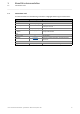
1 About this documentation 1.2 Conventions used ________________________________________________________________ 1.2 Conventions used This documentation uses the following conventions to highlight different types of information: Type of information Writing Examples/notes Spelling of numbers Decimal Decimal separator Hexadecimal Binary • Nibble Normal spelling Point 0x[0 ... 9, A ... F] 0b[0, 1] Example: 1234 The decimal point is always used. For example: 1234.
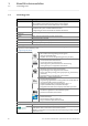
1 About this documentation 1.3 Terminology used ________________________________________________________________ 1.3 Terminology used Term Meaning Controller The controller is the central component of the automation system which controls the Logic and Motion functionalities by means of the runtime software. The controller communicates with the field devices via the fieldbus.
1 About this documentation 1.3 Terminology used ________________________________________________________________ Term Meaning EtherCAT® (Ethernet for Controller and Automation Technology) is an Ethernet-based fieldbus system which fulfils the application profile for industrial real-time systems. EtherCAT® is a registered trademark and patented technology, licensed by Beckhoff Automation GmbH, Germany.
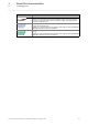
1 About this documentation 1.4 Definition of the notes used ________________________________________________________________ 1.
2 Safety instructions ________________________________________________________________ 2 Safety instructions Observe the following safety instructions before you want to commission an inverter or a system. Read the documentation supplied with the respective product system thoroughly before starting commissioning of the devices.
3 Controller-based Automation: central motion control ________________________________________________________________ 3 Controller-based Automation: central motion control The Lenze automation system "Controller-based Automation" serves to create complex automation solutions with central motion control. Here, the Controller is the control centre of the system.
3 Controller-based Automation: central motion control ________________________________________________________________ Lenze provides especially coordinated system components: • Engineering software The Lenze Engineering tools ( 15) on your Engineering PC (Windows operating system) serve to parameterise, configure and diagnose the system. The Engineering PC communicates with the Controller via Ethernet.
3 Controller-based Automation: central motion control ________________________________________________________________ Fieldbus communication The Lenze Controllers have different interfaces for fieldbus communication: Area Cabinet Controller c300 3221 C 3231 C Panel Controller 3241 C p300 p500 Interfaces (on board) Ethernet 1 2 1 2 EtherCAT 1 1) 1 1 1) 1 CANopen 1 2) - 1 2) - Optional interfaces (communication cards) CANopen MC-CAN2 - - PROFIBUS master MC-PBM - - PR
4 System components 4.1 Engineering tools ________________________________________________________________ 4 System components This chapter describes the single components of the Lenze Controller-based Automation" system. The system consists of an Engineering PC, a Controller and devices which communicate with the Controller via the fieldbus. 4.1 Engineering tools The Engineering PC is a PC/laptop with a Windows operating system and a network connection.
4 System components 4.1 Engineering tools ________________________________________________________________ »EASY Navigator«: Starting the suitable Engineering tool The Lenze Engineering software consists of the Engineering tools optimised for the respective Engineering phase. The »EASY Navigator« shows the Lenze Engineering tools installed on the Engineering PC. Start the desired Engineering tool via the corresponding button: The »EASY Navigator« ...
4 System components 4.1 Engineering tools ________________________________________________________________ Depending on which device you want to use, the suitable Engineering tool has to be started.
4 System components 4.1 Engineering tools ________________________________________________________________ Which device? What would you like to do? Which Engineering tool do you need? Button/icon in the EASY Navigator »EASY Starter« »Enginee r« »PLC Designer « »VisiWin NET« (V3.
4 System components 4.1 Engineering tools ________________________________________________________________ 4.1.2 »EASY Starter« (Online parameterisation and diagnostics) Read parameters »EASY Starter« is an easy-to-use tool for service technicians. The functional range for the commissioning and diagnostics of Lenze devices has been optimised. • Online parameterisation and diagnostics: The »EASY Starter« serves to parameterise/diagnose the Lenze devices with an active online connection.
4 System components 4.1 Engineering tools ________________________________________________________________ 4.1.3 »PLC Designer« (programming, parameter setting, diagnostics) The »PLC Designer« is required to... • create the PLC (control) program of the Controller; • transmit the PLC projects to the Controller; • set parameters of/diagnose the Servo Inverter i700; • configure the bus systems (EtherCAT, CANopen, PROFIBUS, PROFINET).
4 System components 4.1 Engineering tools ________________________________________________________________ 4.1.
4 System components 4.1 Engineering tools ________________________________________________________________ 4.1.
4 System components 4.1 Engineering tools ________________________________________________________________ 4.1.6 Lenze FAST Lenze FAST (Feasibly Applicable Software Toolbox) provides standard software modules for basic drive functions which serve to develop a modular machine control quickly and efficiently. Lenze FAST is integrated in the »PLC Designer«. The FAST modules are autonomous and can be exchanged easily and tested completely independently.
4 System components 4.1 Engineering tools ________________________________________________________________ 4.1.7 »VisiWinNET®« (visualisation) »VisiWinNET®« is a Lenze engineering tool for visualising Lenze automation systems. • »VisiWinNET®« serves to create visualisation and user interfaces for the Lenze automation system. • »VisiWinNET®« consists of the Engineering tool on the Engineering PC and the "Visu" runtime software of the controller.
4 System components 4.1 Engineering tools ________________________________________________________________ 4.1.8 »Backup & Restore« (data backup/restore) »Backup & Restore« is a Lenze software for backing up/restoring data of the Controller and for updating the software/firmware.
4 System components 4.2 Central management of data (parameter settings) ________________________________________________________________ 4.2 Central management of data (parameter settings) The Controller manages the parameter settings centrally and writes them into the corresponding Lenze device.
4 System components 4.3 Controller: The control centre of the Controller-based Automation ________________________________________________________________ 4.3 Controller: The control centre of the Controller-based Automation Cabinet controllers: Compact control cabinet design Cabinet controllers are designed for the demanding continuous use in industrial applications. Compared to panel controllers, they are not equipped with an integrated display.
4 System components 4.
4 System components 4.3 Controller: The control centre of the Controller-based Automation ________________________________________________________________ 4.3.
4 System components 4.3 Controller: The control centre of the Controller-based Automation ________________________________________________________________ 4.3.2 Technical data Cabinet Controller Area Cabinet Controller c300 3221 C Cortex™-A8 800 MHz ATOM™ 1.1 GHz 3231 C 3241 C Processor type Fanless ATOM™ 1.
4 System components 4.3 Controller: The control centre of the Controller-based Automation ________________________________________________________________ Panel Controller Area Panel Controller p300 p500 Screen Diagonal measurement Resolution [pixel] 10.9 cm (4.3") 17.8 cm (7.0") 26.4 cm (10.4") 17.8 cm (7.0") 26.4 cm (10.4") 38.1 cm (15.
4 System components 4.4 Runtime software of the Lenze Controllers ________________________________________________________________ 4.4 Runtime software of the Lenze Controllers By default, the runtime software is installed in the Lenze Controller as "Logic" mode for the central control of PLC applications. Optionally, the "Motion" mode is available, additionally enabling extensive motion control of Motion functions. The inverter then only acts as an actuating drive.
4 System components 4.4 Runtime software of the Lenze Controllers ________________________________________________________________ 4.4.1 "Logic" runtime software "Logic" refers to the use of logically combined control signals without Motion functions. When the "Logic" mode is used, the controller solely controls the motion sequences via logically combined control signals. Functionality • Programming PLC functionality according to IEC 61131-3. • SoftPLC functionality for executing PLC programs.
4 System components 4.4 Runtime software of the Lenze Controllers ________________________________________________________________ 4.4.3 "Visu" runtime software The "Controller-based Automation" system enables the central visualisation of the automation system. The visualisation can either run on a separate Controller or monitor panel or on the Controller on which the "Logic" or "Motion" runtime software is running.
4 System components 4.4 Runtime software of the Lenze Controllers ________________________________________________________________ 4.4.3.1 [4-1] Sample topology 1: External monitor panel/display for cabinet controllers Sample topology: Controller 3231 C with an external monitor panel (connected to the DVI interface) This topology with regard to its performance corresponds to the implemented solution (control/ visualisation on the same controller).
4 System components 4.4 Runtime software of the Lenze Controllers ________________________________________________________________ 4.4.3.2 [4-2] Sample topology 2: Separate control and visualisation Sample topology: Controller 3200 C as gateway for the Visualisation Controller (IPC) The Visualisation Controller (IPC) accesses the field devices via the Controller 3200 C as gateway. In order to separate the control and visualisation, the integrated gateway function of the controller can be used.
4 System components 4.4 Runtime software of the Lenze Controllers ________________________________________________________________ 4.4.3.3 [4-3] Sample topology 3: Independent control and visualisation (CANopen) Sample configuration: Parallel access of Controller 3200 C and Visualisation Controller (IPC) If this topology is used, the Controller 3200 C and the Visualisation Controller (IPC) access the fieldbus independently of each other.
4 System components 4.4 Runtime software of the Lenze Controllers ________________________________________________________________ 4.4.4 Lenze devices (Motion/Logic) for Controller-based Automation Basically, the "Controller-based Automation" system consists of a Controller as the central component and inverters designed for the system (e.g. Servo Inverters i700). • Moreover, the Lenze devices mentioned in the following sections can be used in connection with the Controller-based Automation.
4 System components 4.5 Bus systems ________________________________________________________________ 4.5 Bus systems Bus system Description Standard topology: EtherCAT "on board" The controller (as the central control component) by default communicates with the subordinate field devices via EtherCAT.
4 System components 4.5 Bus systems ________________________________________________________________ 4.5.1 EtherCAT Note! For the Controller c300/p300, the EtherCAT communication is currently being prepared. EtherCAT is an Ethernet-based bus system which provides for Logic and Motion functions on one common fieldbus. • According to the EtherCAT specification, (theoretically) up to 65535 nodes can be connected to an EtherCAT line.
4 System components 4.5 Bus systems ________________________________________________________________ 4.5.2 EtherCAT combined with CANopen Note! Controllers c300/p300 ... • are equipped with an integrated CAN communication interface (on board); • only support the CAN master functionality. The optional MC-CAN2 communication card is not supported by the Controllers c300/ p300.
4 System components 4.5 Bus systems ________________________________________________________________ CANopen: Devices with Logic/Motion functions on separate CAN bus lines The "Controller-based Automation" system supports Lenze field devices with a CANopen interface. This serves to, for instance, control Lenze devices which are provided with a "CAN on board" interface. • To extend the limits of the CAN bus, several CAN lines that are synchronised with regard to each other can be used.
4 System components 4.5 Bus systems ________________________________________________________________ 4.5.3 EtherCAT combined with PROFIBUS Note! Controller c300/p300 do not support PROFIBUS communication. The "Controller-based Automation" system supports further bus systems in the optional mixed operation in order to make it possible to integrate further field devices. The EtherCAT bus system can be used in combination with PROFIBUS. This is reasonable if ...
4 System components 4.5 Bus systems ________________________________________________________________ Physical structure • With an installed (optional) MC-PBM communication card, the Controller 3200 C/p500 is the PROFIBUS master which can communicate with one or several nodes (slaves). • The optional MC-PBS communication card enables the Controller 3200 C/p500 to be operated as PROFIBUS as well. • PROFIBUS either has an internal line topology (without repeater) or a tree topology (with repeater).
4 System components 4.5 Bus systems ________________________________________________________________ 4.5.4 EtherCAT combined with PROFINET (Lenze Controller as slave) Note! In the Lenze automation system, no PROFINET master functionality is supported. In a PROFINET network, a Lenze Controller can only be driven as I/O device (slave), e.g. by a Siemens SIMATIC S7 PLC. For this purpose, the optional MC-PND communication card has to be installed in the Controller.
4 System components 4.5 Bus systems ________________________________________________________________ PROFINET (Logic) The PROFINET bus system is a real-time capable, Ethernet-based bus system. Lenze Controllers support logic functions when the PROFINET bus system is used. PROFINET is recommendable for the following applications: • Extension and control of system parts that have already been automated with PROFINET and another control system.
5 System architecture 5.1 Communication link between Engineering PC and field devices ________________________________________________________________ 5 System architecture By means of the Engineering PC, you commission one or several Controllers. For this purpose, install Engineering tools ( 15) required for commissioning, parameter setting, configuration and diagnostics of the Lenze automation system on the Engineering PC.
5 System architecture 5.2 Online connection via the gateway function of the controller via CAN/EtherCAT ________________________________________________________________ 5.2 Online connection via the gateway function of the controller via CAN/EtherCAT Which Engineering tool do I need? Connection via the network connection (LAN/ Ethernet) of the Engineering PC and the controller. • The Engineering PC receives the data of the field level via the Ethernet connection to the controller.
5 System architecture 5.2 Online connection via the gateway function of the controller via CAN/EtherCAT ________________________________________________________________ Advantage Disadvantage A simple connection without fieldbus-specific adapters is possible. The controller ... • s the master for the fieldbus. • controls the real-time capability of the bus. • controls the access to the fieldbus. This ensures that the fieldbus is always available for the control if required.
5 System architecture 5.3 Direct connection ________________________________________________________________ 5.3 Direct connection A direct connection is available depending on the device. Advantage Disadvantage Provides for a fast data transmission. • The Engineering PC may affect the real-time capability of the controller by a high utilisation of the fieldbus. Example: The Engineering PC sends telegrams, whereas the controller transmits synchronisation protocols.
5 System architecture 5.3 Direct connection ________________________________________________________________ 5.3.1 i700 servo inverter: Which Engineering tool do I need? The i700 servo inverter enables the direct connection via the EtherCAT interface on the device. This provides for a fast connection without the use of further adapters. »EASY Starter« Lenze · Controller-based Automation · System Manual · DMS 1.
5 System architecture 5.3 Direct connection ________________________________________________________________ 5.3.2 Device series 8400/9400: Which Engineering tool do I need? For a direct connection to the 8400/9400 device series, the Engineering PC requires fieldbus-specific adapters. Example: A diagnostic adapter for direct connection of the Engineering PC to an inverter with diagnostics interface.
6 Commissioning of the system: standard procedure ________________________________________________________________ 6 Commissioning of the system: standard procedure In this chapter you'll learn which basic steps you have to carry out to commission a Lenze automation system with a controller. The overview in the table shows which Engineering tool is required in the corresponding commissioning step.
6 Commissioning of the system: standard procedure ________________________________________________________________ What would you like to do? Description Which Lenze Engineering tool? »EASY Starter« »Enginee r« »PLC Designer « »VisiWin NET« V3.x Field devices commissioning • Use the gateway function of the controller to parameterise the field devices.
7 Remote maintenance and diagnostics 7.1 Remote maintenance with an external router ________________________________________________________________ 7 Remote maintenance and diagnostics For a remote maintenance of a Controller, the standard mechanisms for remote maintenance of a PC can be used. The standard mechanisms ... • are based on Ethernet protocol and the protocols used for Ethernet; • can be used between the Engineering/remote maintenance PC (Remote PC) and the corresponding controller.
7 Remote maintenance and diagnostics 7.2 Remote maintenance with a separate remote PC ________________________________________________________________ 7.2 Remote maintenance with a separate remote PC [7-1] Note! Setting a remote maintenance may endanger the IT safety! • This is particularly relevant if the remote PC is connected to an Ethernet network. • Contact your IT administrator to take the necessary safety measures.
7 Remote maintenance and diagnostics 7.3 Computer access via Telnet ________________________________________________________________ 7.3 Computer access via Telnet Telnet is a standard mechanism for experts to change system settings. Telnet ... • enables the access to the Controller data (example: Contents of the SD card); • requires an existing local connection or remote connection. 7.4 Note! Controller c300/p300: • These devices come with a deactivated Telnet in the Lenze standard setting.
7 Remote maintenance and diagnostics 7.5 Web server/»WebConfig« ________________________________________________________________ 7.5 Web server/»WebConfig« The Lenze controllers are provided with an integrated web server. The web server makes it possible to parameterise the controller via »WebConfig«. • The controller parameters can be displayed/altered via web browser.
7 Remote maintenance and diagnostics 7.6 »Virtual Network Computing (VNC)«: Redirecting screen contents/entries ________________________________________________________________ 7.6 »Virtual Network Computing (VNC)«: Redirecting screen contents/entries For remote maintenance of a controller, the screen content can be redirected to the Engineering PC. This makes it possible to view all keyboard entries/mouse movement of the local PC on the remote PC.
8 Appendix 8.1 Communication by means of OPC ________________________________________________________________ 8 Appendix 8.1 Communication by means of OPC Note! There is no OPC server available for PROFIBUS and PROFINET. Controller c300/p300: • The OPC communication for »VisiWinNET« is exclusively available for Controller p300 without PLC. • Otherwise, only the Lenze "Logic&Motion" direct driver can be used for the data exchange between »VisiWinNET« and PLC.
8 Appendix 8.1 Communication by means of OPC ________________________________________________________________ 8.1.2 OPC as universal driver OPC is a universal driver of the OPC Data Access specification in the automation technology. • The universal driver encapsulates the original driver and provides the generally understandable services via a universal interface. • When accessing the field level, the OPC client comes upon a uniform interface. 8.1.
8 Appendix 8.1 Communication by means of OPC ________________________________________________________________ 8.1.4 OPC tunnel If an OPC server and an OPC client are located on different computers, OPC tunnels are used. This is a software which is installed on both computers and which acts as client/server itself. The OPC tunnel for example uses the TCP/IP protocol to transfer the data between the OPC server and OPC client.
9 Glossary ________________________________________________________________ 9 Glossary A Application Implementation of a precise function/drive solution (e.g. speed control) on an individual device. Application Samples Predefined application samples/sample projects for commissioning Lenze inverters. Application templates Lenze application template for creating standardised modular applications in the »PLC Designer«. Bus server Fieldbus-specific OPC server according to DRIVECOM specification.
9 Glossary ________________________________________________________________ D DCOM Abbreviation for "Distributed Component Object Model": COM where the executable objects are distributed to different computers within one local area network. COM ( 63) DRIVECOM "DRIVECOM User Group e.V.": International organisation of manufacturers of drive technology, universities and institutes with the target to develop an easy integration of drives into open automation structures. Internet: www.drivecom.
Index ________________________________________________________________ A I Application notes 10 Application Samples 22 Application templates 22 Interfaces for fieldbus communication 14, 28 L Backup & Restore 25 Bus systems 39 Layout of the safety instructions 10 Lenze FAST 23 Logic (runtime software) 33 Logic devices 38 C M Cabinet Controller 27 Cabinet Controller (technical data) 30 CANopen 41, 42 Central data management 26 Communication link between Engineering PC and field devices 47 Computer a
Index ________________________________________________________________ T Target group 5 Technical data, Cabinet Controller 30 Technical data, Panel Controller 31 telnet 57 Terminology used 8 V Virtual Network Computing (VNC) 59 VisiWinNET 24 Visu (runtime software) 34 Visualising with »VisiWinNET®« 24 VNC viewer software 59 W Web server/»WebConfig« 58 WebConfig 18 66 Lenze · Controller-based Automation · System Manual · DMS 1.
)(('%$&. Your opinion is important to us These instructions were created to the best of our knowledge and belief to give you the best possible support for handling our product. Perhaps we have not succeeded in achieving this objective in every respect. If you have suggestions for improvement, please e-mail us to: feedback-docu@lenze.com Thank you very much for your support.
Controller-based Automation · System Manual · GHBSTV3LM-001 · 13461044 · DMS 1.4 EN · 04/2014 · TD17 Lenze Automation GmbH Postfach 10 13 52, D-31763 Hameln Hans-Lenze-Straße 1, D-31855 Aerzen Germany +49 5154 82-0 +49 5154 82-2800 lenze@lenze.com www.lenze.com Service Lenze Service GmbH Breslauer Straße 3, D-32699 Extertal Germany 008000 24 46877 (24 h helpline) +49 5154 82-1112 service@lenze.