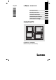
L−force Controls Ä.NGCä MA_CSx0xx .NGC Montageanleitung Mounting Instructions Instructions de montage Instrucciones para el montaje Istruzioni per il montaggio Industrial PC Power Fail Status Power Fail Status F1 F1 F2 + F2 - F3 + F3 / ( 7 - ) 8 - 9 $ & 4 5 § " 2 = 3 > < , 0 + 6 ! 1 * A B 8 7 / | F 5 Fail J 1 .
Lesen Sie zuerst diese Anleitung, bevor Sie mit den Arbeiten beginnen! Beachten Sie die enthaltenen Sicherheitshinweise. Ausführliche Informationen finden Sie in der Betriebsanleitung. Read these instructions before you start working! Follow the safety instructions given. More detailed information can be found in the Operating Instructions. Veuillez lire attentivement cette documentation avant toute action ! Les consignes de sécurité doivent impérativement être respectées.
Inhalt 1 3 4 5 i Über diese Dokumentation . . . . . . . . . . . . . . . . . . . . . . . . . . . . . . . . . . . . . . . . . 4 1.1 Verwendete Hinweise . . . . . . . . . . . . . . . . . . . . . . . . . . . . . . . . . . . . . . . 4 Sicherheitshinweise . . . . . . . . . . . . . . . . . . . . . . . . . . . . . . . . . . . . . . . . . . . . . . . 5 3.1 3.2 5 6 Allgemeine Sicherheitshinweise . . . . . . . . . . . . . . . . . . . . . . . . . . . . . .
1 Über diese Dokumentation Verwendete Hinweise 0Abb. 0Tab. 0 1 Über diese Dokumentation 1.
Sicherheitshinweise 2 Allgemeine Sicherheitshinweise 2 Sicherheitshinweise 2.1 Allgemeine Sicherheitshinweise Auch zu Ihrer eigenen Sicherheit Gefahr! Wenn Sie die folgenden grundlegenden Sicherheitsmaßnahmen missachten, kann dies zu schweren Personenschäden und Sachschäden führen: ƒ Lenze−Antriebs− und Automatisierungskomponenten ... ... ausschließlich bestimmungsgemäß verwenden. ... niemals trotz erkennbarer Schäden in Betrieb nehmen. ... niemals technisch verändern. ...
2 Sicherheitshinweise Sicherheitshinweise für die Installation nach UL 2.2 Sicherheitshinweise für die Installation nach UL Original − Englisch Approval Underwriter Laboratories (UL), UL508 and CSA C22.2 No. 142−M1987, (UL File Number E236341) 6 MA_CSx0xx DE/EN/FR/ES/IT 2.
Sicherheitshinweise 2 Sicherheitshinweise für die Installation nach UL Ratings ƒ ƒ ƒ ƒ Input 24 V DC, max. 65 W (65 VA) Max. ambient temperature 40 °C Environmental ratings: Type 1 Enclosure Optional communication ratings: – RS232−Connection: max. 3 A – USB−Connection, PS/2−Connection: max. 1 A – LAN−Connection: Standard ISDN or RJ45 – VGA−Connection, FBAS−Connection, DVI−Connector, DPL−Connection: max. 4 A – External Power Supply for DVI/USB Extender: max.
2 Sicherheitshinweise Sicherheitshinweise für die Installation nach UL Original − Französisch Homologation Underwriter Laboratories (UL), UL508 et CSA C22.2 n° 142−M1987, (n° de dossier UL E236341) 8 MA_CSx0xx DE/EN/FR/ES/IT 2.
Sicherheitshinweise 2 Sicherheitshinweise für die Installation nach UL Caractéristiques assignées ƒ ƒ ƒ ƒ Entrée 24 V CC, maximum 65 W (65 VA) Température ambiante maximale : 40 °C Evaluation environnementale : coffret de type 1 Caractéristiques de communication assignées (option) : – Port RS232 : maximum 3 A – Port USB, port PS/2 : maximum 1 A – Port LAN : RNIS standard ou RJ45 – Port VGA, port FBAS, connecteur DVI, port DPL : maximum 4 A – Alimentation externe pour carte d’extension DVI/USB : maximum
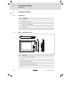
3 Produktbeschreibung Lieferumfang 3 Produktbeschreibung 3.1 Lieferumfang 3.2 Anzahl Bezeichnung 1 Monitor Panel 1 Anschlussstecker für Spannungsversorgung 1 DVI−D−Kabel (Länge 2 m) 1 USB−Kabel (Länge 2 m) 1 Befestigungsadapter (Option) 1 DVD "PC based Automation" 1 Testbericht 1 Gerätepass Bedien− und Anzeigeelemente 0 1 6 2 7 F2 + F3 - 4 DVI USB-A USB-B 24 V DC 0V F1 3 U + Power Fail Status 5 CS50x0−001 Pos.
Installation 4 Wichtige Hinweise 4 Installation 4.1 Wichtige Hinweise Stop! Empfindlicher Dichtring am Frontrahmen Während der Montage liegt der Dichtring des Frontrahmens frei und kann beschädigt werden. Mögliche Folgen: ƒ Die in den Technischen Daten genannte Schutzart wird nicht erreicht. Schutzmaßnahmen: ƒ Gehen Sie während der Montage sorgsam mit dem Dichtring um. ƒ Schützen Sie den Dichtring vor UV−Strahlen.
4 Installation Montageschritte Montagewanne demontieren 4.2 Montageschritte 4.2.1 Montagewanne demontieren 0 1 0V 0 0 2 U 0V U CS50xx−004 So gehen Sie vor: 1. Gerät flach, mit der Montagewanne oben, auf eine mit einer Decke gepolsterte Arbeitsfläche legen. – Die Arbeitsfläche muss stabil, ausreichend groß und frei von jeglichen Gegenständen sein. Der Touchscreen wird beschädigt, wenn er auf Gegenstände, wie zum Beispiel Schrauben, gelegt wird. 2.
Installation 4 Montageschritte Montagewanne an Tragarm montieren 4.2.2 Montagewanne an Tragarm montieren Ohne Anbauelement 1 3 1 0 1 6 2 CS57x0−005 So gehen Sie vor: 1. Tragarmsystem auf fachgerechte Montage und ausreichende Tragfähigkeit prüfen. – Siehe Tragarm−Dokumentation. 2. Die selbstklebende Dichtung auf die Adapterplatte , auf die Seite mit den Gewindebolzen, kleben. 3. Die Anschlusskabel aus dem Tragarm ziehen und die Adapterplatte an den Tragarm schrauben.
4 Installation Montageschritte Montagewanne an Tragarm montieren Mit Anbauelement 1 0 4 3 1 1 4 5 2 0 4 6 CS57x0−006 So gehen Sie vor: 1. Tragarmsystem auf fachgerechte Montage und ausreichende Tragfähigkeit prüfen. – Siehe Tragarm−Dokumentation. 2. Die selbstklebende Dichtung auf die Adapterplatte , auf die Seite mit den Gewindebolzen, kleben. 3. Die Anschlusskabel aus dem Tragarm ziehen und die Adapterplatte an den Tragarm schrauben. – Schrauben siehe Tragarm−Dokumentation. 4.
Installation 4 Montageschritte Montagewanne an Wand montieren 4.2.3 Montagewanne an Wand montieren Ohne Anbauelement 1 2 0 0 106 29.5 160 2 3 70 6 3 3 CS57x0−010 So gehen Sie vor: 1. Wand für die Montage der Wandhalterung vorbereiten. – Der Montageort und das Montagematerial muss die mechanische Verbindung dauerhaft gewährleisten. 2. Die selbstklebende Dichtung auf die Adapterplatte , auf die Seite mit den Gewindebolzen, kleben. 3.
4 Installation Montageschritte Montagewanne an Wand montieren Mit Anbauelement 2 1 0 0 106 29.5 160 2 3 70 4 3 5 3 4 1 4 6 CS57x0−011 So gehen Sie vor: 1. Wand für die Montage der Wandhalterung vorbereiten. – Der Montageort und das Montagematerial muss die mechanische Verbindung dauerhaft gewährleisten. 2. Die selbstklebende Dichtung auf die Adapterplatte , auf die Seite mit den Gewindebolzen, kleben. 3. Wandhalterung und die Adapterplatte an den Schwenkadapter schrauben.
Installation 4 Elektrische Installation 4.3 Elektrische Installation Anschlussplan Versorgung L1 N PE S F 0 1 L1 N 0 V PE +24 V + ~ 2 + = 0V + +24 + CS50x0−021 Montagewanne Bildschirm Netzteil Hinweis! Beachten Sie die maximal zulässige Eingangsspannung. Sichern Sie das Gerät eingangsseitig fachgerecht gegen Spannungsschwankungen und −spitzen ab.
4 Installation Elektrische Installation 1 3 } 4 U U } 0V 2 0V 0 + max. 12 kg 1 } 0 1 0V U 0 } CS50x0−012 So gehen Sie vor: 1. Bildschirm mit der Einhängung in die Montagewanne setzen und während der folgenden Arbeitsschritte gegen Herunterfallen sichern. 2. Anschlusskabel stecken. – PE−Anschlusskabel an der Montagewanne stecken – Sonstige Anschlusskabel stecken (Versorgung, DVI, USB). 3. Bildschirm einklappen. 4. Bildschirm an der Montagewanne verschrauben.
Contents 1 3 4 5 i About this documentation . . . . . . . . . . . . . . . . . . . . . . . . . . . . . . . . . . . . . . . . . . 20 1.1 Notes used . . . . . . . . . . . . . . . . . . . . . . . . . . . . . . . . . . . . . . . . . . . . . . . . 20 Safety instructions . . . . . . . . . . . . . . . . . . . . . . . . . . . . . . . . . . . . . . . . . . . . . . . . 21 3.1 3.2 General safety information . . . . . . . . . . . . . . . . . . . . . . . . . . . . . . . . . . .
1 About this documentation Notes used 0Fig. 0Tab. 0 1 About this documentation 1.
Safety instructions 2 General safety information 2 Safety instructions 2.1 General safety information For your own safety Danger! Disregarding the following basic safety measures may lead to severe personal injury and damage to material assets! ƒ Lenze drive and automation components ... ... must only be used for the intended purpose. ... must never be operated if damaged. ... must never be subjected to technical modifications. ... must never be operated unless completely assembled. ...
2 Safety instructions Safety instructions for the installation according to UL 2.2 Safety instructions for the installation according to UL Original − English Approval Underwriter Laboratories (UL), UL508 and CSA C22.2 No. 142−M1987, (UL File Number E236341) 22 MA_CSx0xx DE/EN/FR/ES/IT 2.
Safety instructions 2 Safety instructions for the installation according to UL Ratings ƒ ƒ ƒ ƒ Input 24 V DC, max. 65 W (65 VA) Max. ambient temperature 40 °C Environmental ratings: Type 1 Enclosure Optional communication ratings: – RS232−Connection: max. 3 A – USB−Connection, PS/2−Connection: max. 1 A – LAN−Connection: Standard ISDN or RJ45 – VGA−Connection, FBAS−Connection, DVI−Connector, DPL−Connection: max. 4 A – External Power Supply for DVI/USB Extender: max.
2 Safety instructions Safety instructions for the installation according to UL Original − French Homologation Underwriter Laboratories (UL), UL508 et CSA C22.2 n° 142−M1987, (n° de dossier UL E236341) 24 MA_CSx0xx DE/EN/FR/ES/IT 2.
Safety instructions 2 Safety instructions for the installation according to UL Caractéristiques assignées ƒ ƒ ƒ ƒ Entrée 24 V CC, maximum 65 W (65 VA) Température ambiante maximale : 40 °C Evaluation environnementale : coffret de type 1 Caractéristiques de communication assignées (option) : – Port RS232 : maximum 3 A – Port USB, port PS/2 : maximum 1 A – Port LAN : RNIS standard ou RJ45 – Port VGA, port FBAS, connecteur DVI, port DPL : maximum 4 A – Alimentation externe pour carte d’extension DVI/USB :
3 Product description Scope of supply 3 Product description 3.1 Scope of supply Quantity Name 3.2 1 Monitor panel 1 Connection plug for voltage supply 1 DVI−D cable (length 2 m) 1 USB cable (length 2 m) 1 Fixing adapter (option) 1 DVD "PC based Automation" 1 Test report 1 Device pass card Controls and displays 0 1 6 2 7 F2 + F3 - 4 DVI USB-A USB-B 24 V DC 0V F1 3 U + Power Fail Status 5 CS50x0−001 Pos.
Installation 4 Important notes 4 Installation 4.1 Important notes Stop! Sensitive front frame gasket During mounting, the gasket of the front frame is exposed and can be damaged. Possible consequences: ƒ The degree of protection provided by the enclosure mentioned in the technical data is not attained. Protective measures: ƒ Handle the gasket with care during mounting. ƒ Protect the gasket against ultraviolet rays. ƒ Each time before you mount the device, check whether the gasket is intact.
4 Installation Mounting steps Removing the mounting frame 4.2 Mounting steps 4.2.1 Removing the mounting frame 0 1 0V 0 0 2 U 0V U CS50xx−004 How to proceed: 1. Lay the device flat, with the mounting frame upwards, on a work surface cushioned with a blanket. – The work surface must be stable, sufficiently large, and free of any objects. The touchscreen will be damaged when being laid on objects as for instance screws. 2. Remove screws from the mounting frame. 3.
Installation 4 Mounting steps Fixing the mounting frame to the support arm 4.2.2 Fixing the mounting frame to the support arm Without add−on component 1 3 1 0 1 6 2 CS57x0−005 How to proceed: 1. Check support arm system for professional mounting and sufficient carrying capacity. – See support arm documentation. 2. Stick the self−adhesive seal on the adapter plate on the side with the threaded bolts. 3.
4 Installation Mounting steps Fixing the mounting frame to the support arm With add−on component 1 0 4 3 1 1 4 5 2 0 4 6 CS57x0−006 How to proceed: 1. Check support arm system for professional mounting and sufficient carrying capacity. – See support arm documentation. 2. Stick the self−adhesive seal on the adapter plate on the side with the threaded bolts. 3. Pull the connecting cables out of the support arm and screw the adapter plate to the support arm .
Installation 4 Mounting steps Fixing the mounting frame to the wall 4.2.3 Fixing the mounting frame to the wall Without add−on component 1 2 0 0 106 29.5 160 2 3 70 6 3 3 CS57x0−010 How to proceed: 1. Prepare the wall for mounting the wall bracket . – The mounting location and the installation material must provide for a permanent mechanical connection. 2. Stick the self−adhesive seal on the adapter plate on the side with the threaded bolts. 3.
4 Installation Mounting steps Fixing the mounting frame to the wall With add−on component 2 1 0 0 106 29.5 160 2 3 70 4 3 5 3 4 1 4 6 CS57x0−011 How to proceed: 1. Prepare the wall for mounting the wall bracket . – The mounting location and the installation material must provide for a permanent mechanical connection. 2. Stick the self−adhesive seal on the adapter plate on the side with the threaded bolts. 3.
Installation 4 Electrical installation 4.3 Electrical installation Terminal diagram supply L1 N PE S F 0 1 L1 N 0 V PE +24 V + ~ 2 + = 0V + +24 + CS50x0−021 Mounting frame Screen Power supply unit Note! Observe the max. permissible input voltage. Professionally fuse the device on the input side against voltage variations and voltage peaks.
4 Installation Electrical installation 1 3 } 4 U U } 0V 2 0V 0 + max. 12 kg 1 } 0 1 0V U 0 } CS50x0−012 How to proceed: 1. Place screen in the mounting frame using the attachment and secure it against falling down during the following worksteps. 2. Plug in the connection cable . – Plug in the PE connection cable on the mounting frame – Plug in other connection cables (supply, DVI, USB). 3. Retract screen. 4. Screw screen to the mounting frame. Always fit all screws.
Sommaire 1 3 4 5 i Présentation du document . . . . . . . . . . . . . . . . . . . . . . . . . . . . . . . . . . . . . . . . . 36 1.1 Consignes utilisées . . . . . . . . . . . . . . . . . . . . . . . . . . . . . . . . . . . . . . . . . 36 Consignes de sécurité . . . . . . . . . . . . . . . . . . . . . . . . . . . . . . . . . . . . . . . . . . . . . . 37 3.1 3.2 Consignes générales de sécurité . . . . . . . . . . . . . . . . . . . . . . . . . . . . . . .
1 Présentation du document Consignes utilisées 0Fig. 0Tab. 0 1 Présentation du document 1.1 Consignes utilisées Pour indiquer des risques et des informations importantes, la présente documentation utilise les mots et pictogrammes suivants : Consignes de sécurité Présentation des consignes de sécurité Danger ! (Le pictogramme indique le type de risque.) Explication (L’explication décrit le risque et les moyens de l’éviter.
Consignes de sécurité 2 Consignes générales de sécurité 2 Consignes de sécurité 2.1 Consignes générales de sécurité Conseils pour assurer votre sécurité Danger ! Le non−respect des consignes fondamentales de sécurité suivantes peut entraîner des blessures et des dommages matériels graves. ƒ Les composants d’entraînement et d’automatisation Lenze ... ... doivent exclusivement être utilisés conformément à leur fonction. ... ne doivent jamais être mis en service si des dommages sont décelés. ...
2 Consignes de sécurité Consignes de sécurité pour l’installation selon UL 2.2 Consignes de sécurité pour l’installation selon UL Original − Anglais Approval Underwriter Laboratories (UL), UL508 and CSA C22.2 No. 142−M1987, (UL File Number E236341) 38 MA_CSx0xx DE/EN/FR/ES/IT 2.
Consignes de sécurité 2 Consignes de sécurité pour l’installation selon UL Ratings ƒ ƒ ƒ ƒ Input 24 V DC, max. 65 W (65 VA) Max. ambient temperature 40 °C Environmental ratings: Type 1 Enclosure Optional communication ratings: – RS232−Connection: max. 3 A – USB−Connection, PS/2−Connection: max. 1 A – LAN−Connection: Standard ISDN or RJ45 – VGA−Connection, FBAS−Connection, DVI−Connector, DPL−Connection: max. 4 A – External Power Supply for DVI/USB Extender: max.
2 Consignes de sécurité Consignes de sécurité pour l’installation selon UL Original − Français Homologation Underwriter Laboratories (UL), UL508 et CSA C22.2 n° 142−M1987, (n° de dossier UL E236341) 40 MA_CSx0xx DE/EN/FR/ES/IT 2.
Consignes de sécurité 2 Consignes de sécurité pour l’installation selon UL Caractéristiques assignées ƒ ƒ ƒ ƒ Entrée 24 V CC, maximum 65 W (65 VA) Température ambiante maximale : 40 °C Evaluation environnementale : coffret de type 1 Caractéristiques de communication assignées (option) : – Port RS232 : maximum 3 A – Port USB, port PS/2 : maximum 1 A – Port LAN : RNIS standard ou RJ45 – Port VGA, port FBAS, connecteur DVI, port DPL : maximum 4 A – Alimentation externe pour carte d’extension DVI/USB : maxi
3 Description du produit Equipement livré 3 Description du produit 3.1 Equipement livré Quantité Désignation 3.
Installation 4 Remarques importantes 4 Installation 4.1 Remarques importantes Stop ! Joint d’étanchéité fragile sur cadre avant Pendant les opérations de montage, le joint d’étanchéité du cadre avant n’est pas protégé et risque alors d’être endommagé. Risques encourus : ƒ L’indice de protection indiqué sous "Spécifications techniques" n’est pas atteint. Mesures de protection : ƒ Pendant le montage, manipuler le joint d’étanchéité avec soin. ƒ Protéger le joint d’étancheité contre les rayons UV.
4 Installation Remarques importantes Stop ! Court−circuits et décharges électrostatiques L’appareil comprend des composants sensibles aux court−circuits ou aux décharges électrostatiques. Risques encourus : ƒ Destruction de l’appareil ou de ces composants Mesures de protection : ƒ Veiller à ce que l’appareil soit hors tension avant tous travaux sur celui−ci.
Installation 4 Opérations de montage Démontage du châssis de montage 4.2 Opérations de montage 4.2.1 Démontage du châssis de montage 0 1 0V 0 0 U 2 0V U CS50xx−004 Procéder aux opérations suivantes : 1. Positionner l’appareil à plat, le châssis de montage vers le haut, sur une surface de travail recouverte d’une couverture. – La surface de travail doit être stable, suffisamment grande et exempte de tout objet.
4 Installation Opérations de montage Montage du châssis sur bras porteur 4.2.2 Montage du châssis sur bras porteur Sans élément d’assemblage 1 0 3 1 1 6 2 CS57x0−005 Procéder aux opérations suivantes : 1. Vérifier si le système à bras porteur est correctement monté et si sa capacité de charge est suffisante. – Voir la documentation du bras porteur. 2. Coller le joint autocollant sur la plaque de montage (du côté des goujons filetés). 3.
Installation 4 Opérations de montage Montage du châssis sur bras porteur Avec élément d’assemblage 1 0 4 3 1 1 4 5 2 0 4 6 CS57x0−006 Procéder aux opérations suivantes : 1. Vérifier si le système à bras porteur est correctement monté et si sa capacité de charge est suffisante. – Voir la documentation du bras porteur. 2. Coller le joint autocollant sur la plaque de montage (du côté des goujons filetés). 3.
4 Installation Opérations de montage Montage mural du châssis 4.2.3 Montage mural du châssis Sans élément d’assemblage 1 2 0 0 106 29.5 160 2 3 70 6 3 3 CS57x0−010 Procéder aux opérations suivantes : 1. Préparer le mur pour le montage du dispositif de fixation murale . – Le lieu d’installation et le matériel de montage doivent garantir une liaison mécanique durable. 2. Coller le joint autocollant sur la plaque de montage (du côté des goujons filetés). 3.
Installation 4 Opérations de montage Montage mural du châssis Avec élément d’assemblage 2 1 0 0 106 29.5 160 2 3 70 4 3 5 3 4 1 4 6 CS57x0−011 Procéder aux opérations suivantes : 1. Préparer le mur pour le montage du dispositif de fixation murale . – Le lieu d’installation et le matériel de montage doivent garantir une liaison mécanique durable. 2. Coller le joint autocollant sur la plaque de montage (du côté des goujons filetés). 3.
4 Installation Installation électrique 4.3 Installation électrique Plan de raccordement de l’alimentation L1 N PE S F 0 1 L1 N 0 V PE +24 V + ~ 2 + = 0V + +24 + CS50x0−021 Châssis de montage Ecran Bloc d’alimentation Remarque importante ! Respecter la tension d’entrée maximale admissible. Protéger l’appareil de manière adaptée côté entrée contre les fluctuations de tension et les pointes de tension.
Installation 4 Installation électrique 1 3 } 4 U U } 0V 2 0V 0 + max. 12 kg 1 } 0 1 0V U 0 } CS50x0−012 Procéder aux opérations suivantes : 1. Positionner l’écran avec le dispositif de fixation dans le châssis de montage et procéder aux opérations suivantes afin de le protéger contre les chutes. 2. Enficher le câble de raccordement . – Enficher le câble de raccordement PE dans le châssis de montage. – Enficher les autres câbles de raccordement (alimentation, DVI, USB).
i 1 3 4 5 Contenido Acerca de esta documentación . . . . . . . . . . . . . . . . . . . . . . . . . . . . . . . . . . . . . . 53 1.1 Indicaciones utilizadas . . . . . . . . . . . . . . . . . . . . . . . . . . . . . . . . . . . . . . 53 Instrucciones de seguridad . . . . . . . . . . . . . . . . . . . . . . . . . . . . . . . . . . . . . . . . . 54 3.1 3.2 Instrucciones generales de seguridad . . . . . . . . . . . . . . . . . . . . . . . . . .
Acerca de esta documentación 1 Indicaciones utilizadas 0Fig. 0Tab. 0 1 Acerca de esta documentación 1.
2 Instrucciones de seguridad Instrucciones generales de seguridad 2 Instrucciones de seguridad 2.1 Instrucciones generales de seguridad También para su propia seguridad ¡Peligro! Si no se observan las siguientes instrucciones básicas de seguridad, pueden ocasionarse serios daños a personas y materiales: ƒ Los componentes de accionamiento y automatización de Lenze ... ... sólo deben utilizarse de la manera adecuada. ... nunca deben ponerse en funcionamiento si existen daños visibles. ...
Instrucciones de seguridad 2 Instrucciones de seguridad para la instalación según UL 2.2 Instrucciones de seguridad para la instalación según UL Original − Inglés Approval Underwriter Laboratories (UL), UL508 and CSA C22.2 No. 142−M1987, (UL File Number E236341) MA_CSx0xx DE/EN/FR/ES/IT 2.
2 Instrucciones de seguridad Instrucciones de seguridad para la instalación según UL Ratings ƒ ƒ ƒ ƒ Input 24 V DC, max. 65 W (65 VA) Max. ambient temperature 40 °C Environmental ratings: Type 1 Enclosure Optional communication ratings: – RS232−Connection: max. 3 A – USB−Connection, PS/2−Connection: max. 1 A – LAN−Connection: Standard ISDN or RJ45 – VGA−Connection, FBAS−Connection, DVI−Connector, DPL−Connection: max. 4 A – External Power Supply for DVI/USB Extender: max.
Instrucciones de seguridad 2 Instrucciones de seguridad para la instalación según UL Original − Francés Homologation Underwriter Laboratories (UL), UL508 et CSA C22.2 n° 142−M1987, (n° de dossier UL E236341) MA_CSx0xx DE/EN/FR/ES/IT 2.
2 Instrucciones de seguridad Instrucciones de seguridad para la instalación según UL Caractéristiques assignées ƒ ƒ ƒ ƒ Entrée 24 V CC, maximum 65 W (65 VA) Température ambiante maximale : 40 °C Evaluation environnementale : coffret de type 1 Caractéristiques de communication assignées (option) : – Port RS232 : maximum 3 A – Port USB, port PS/2 : maximum 1 A – Port LAN : RNIS standard ou RJ45 – Port VGA, port FBAS, connecteur DVI, port DPL : maximum 4 A – Alimentation externe pour carte d’extension DVI/U
Descripción del producto 3 Alcance del suministro 3 Descripción del producto 3.1 Alcance del suministro Cantidad Denominación 3.
4 Instalación Indicaciones importantes 4 Instalación 4.1 Indicaciones importantes ¡Alto! Anillo obturador sensible en el marco frontal. Durante el montaje, el anillo obturador del marco frontal queda expuesto y puede resultar dañado. Posibles consecuencias: ƒ No se alcanzará el tipo de protección indicado en los datos técnicos. Medidas de protección: ƒ Tenga cuidado con el anillo obturador durante el montaje. ƒ Proteja el anillo obturador contra rayos UV.
Instalación 4 Indicaciones importantes ¡Alto! Cortocircuito y descargas estáticas El equipo contiene elementos que pueden resultar dañados en caso de cortocircuito o descarga estática. Posibles consecuencias: ƒ El equipo o partes de éste podrían resultar dañados. Medidas de protección: ƒ Siempre desconectar el suministro de voltaje al trabajar en el equipo. Esto es especialmente de aplicación: – antes de enchufar/desenchufar conectores. – antes de enchufar/desenchufar módulos.
4 Instalación Pasos para el montaje Desmontar marco de montaje 4.2 Pasos para el montaje 4.2.1 Desmontar marco de montaje 0 1 0V 0 0 2 U 0V U CS50xx−004 Proceda de la siguiente manera: 1. Colocar el equipo de manera llana, con el marco de montaje hacia arriba, sobre una superficie de trabajo protegida con una manta. – La superficie de trabajo debe ser estable, suficientemente grande y estar libre de cualquier objeto.
Instalación 4 Pasos para el montaje Montar marco de montaje en el brazo portante 4.2.2 Montar marco de montaje en el brazo portante Sin elemento adicional 1 3 1 0 1 6 2 CS57x0−005 Proceda de la siguiente manera: 1. Comprobar que el sistema de brazo portante esté montado correctamente y tenga suficiente capacidad de carga. – Véase la documentación del brazo portante. 2. Pegar la junta autoadhesiva sobre la placa adaptadora , en el lado con el perno roscado. 3.
4 Instalación Pasos para el montaje Montar marco de montaje en el brazo portante Con elemento adicional 1 0 4 3 1 1 4 5 2 0 4 6 CS57x0−006 Proceda de la siguiente manera: 1. Comprobar que el sistema de brazo portante esté montado correctamente y tenga suficiente capacidad de carga. – Véase la documentación del brazo portante. 2. Pegar la junta autoadhesiva sobre la placa adaptadora , en el lado con el perno roscado. 3.
Instalación 4 Pasos para el montaje Montar marco de montaje en la pared 4.2.3 Montar marco de montaje en la pared Sin elemento adicional 1 2 0 0 106 29.5 160 2 3 70 6 3 3 CS57x0−010 Proceda de la siguiente manera: 1. Preparar la pared para el montaje en el soporte de pared . – El lugar y el material de montaje deben garantizar la unión mecánica de forma duradera. 2. Pegar la junta autoadhesiva sobre la placa adaptadora , en el lado con el perno roscado. 3.
4 Instalación Pasos para el montaje Montar marco de montaje en la pared Con elemento adicional 2 1 0 0 106 29.5 160 2 3 70 4 3 5 3 4 1 4 6 CS57x0−011 Proceda de la siguiente manera: 1. Preparar la pared para el montaje en el soporte de pared . – El lugar y el material de montaje deben garantizar la unión mecánica de forma duradera. 2. Pegar la junta autoadhesiva sobre la placa adaptadora , en el lado con el perno roscado. 3.
Instalación 4 Instalación eléctrica 4.3 Instalación eléctrica Esquema de conexiones del suministro L1 N PE S F 0 1 L1 N 0 V PE +24 V + ~ 2 + = 0V + +24 + CS50x0−021 Marco para el montaje Pantalla Fuente de red ¡Aviso! Observe el voltaje de entrada máximo permitido. Asegure el equipo en el lado de entrada de forma adecuada contra oscilaciones y picos de tensión.
4 Instalación Instalación eléctrica 1 3 } 4 U U } 0V 2 0V 0 + max. 12 kg 1 } 0 1 0V U 0 } CS50x0−012 Proceda de la siguiente manera: 1. Colocar la pantalla con el enganche en el marco de montaje y asegurarla contra una posible caída durante los siguientes pasos. 2. Insertar cable de conexión . – Insertar cable de conexión de PE en el marco de montaje. – Insertar los demás cables de conexión (alimentación, DVI, USB). 3. Tapar pantalla. 4.
Sommario 1 3 4 5 i Informazioni sul manuale . . . . . . . . . . . . . . . . . . . . . . . . . . . . . . . . . . . . . . . . . . 70 1.1 Avvertenze utilizzate . . . . . . . . . . . . . . . . . . . . . . . . . . . . . . . . . . . . . . . . 70 Informazioni sulla sicurezza . . . . . . . . . . . . . . . . . . . . . . . . . . . . . . . . . . . . . . . . 71 3.1 3.2 Note generali di sicurezza . . . . . . . . . . . . . . . . . . . . . . . . . . . . . . . . . . . .
1 Informazioni sul manuale Avvertenze utilizzate 0Fig. 0Tab. 0 1 Informazioni sul manuale 1.
Informazioni sulla sicurezza 2 Note generali di sicurezza 2 Informazioni sulla sicurezza 2.1 Note generali di sicurezza Anche per la propria sicurezza Pericolo! La mancata osservanza delle seguenti misure fondamentali di sicurezza può provocare gravi danni a persone e cose.
2 Informazioni sulla sicurezza Informazioni sulla sicurezza per l’installazione secondo UL o UR 2.2 personale che conosce ed è in grado di applicare tutte le disposizioni antinfortunistiche, le direttive e le norme vigenti nel luogo di installazione. Informazioni sulla sicurezza per l’installazione secondo UL o UR Originale − Inglese Approval Underwriter Laboratories (UL), UL508 and CSA C22.2 No. 142−M1987, (UL File Number E236341) 72 MA_CSx0xx DE/EN/FR/ES/IT 2.
Informazioni sulla sicurezza 2 Informazioni sulla sicurezza per l’installazione secondo UL o UR Ratings ƒ ƒ ƒ ƒ Input 24 V DC, max. 65 W (65 VA) Max. ambient temperature 40 °C Environmental ratings: Type 1 Enclosure Optional communication ratings: – RS232−Connection: max. 3 A – USB−Connection, PS/2−Connection: max. 1 A – LAN−Connection: Standard ISDN or RJ45 – VGA−Connection, FBAS−Connection, DVI−Connector, DPL−Connection: max. 4 A – External Power Supply for DVI/USB Extender: max.
2 Informazioni sulla sicurezza Informazioni sulla sicurezza per l’installazione secondo UL o UR Originale − Francese Homologation Underwriter Laboratories (UL), UL508 et CSA C22.2 n° 142−M1987, (n° de dossier UL E236341) 74 MA_CSx0xx DE/EN/FR/ES/IT 2.
Informazioni sulla sicurezza 2 Informazioni sulla sicurezza per l’installazione secondo UL o UR Caractéristiques assignées ƒ ƒ ƒ ƒ Entrée 24 V CC, maximum 65 W (65 VA) Température ambiante maximale : 40 °C Evaluation environnementale : coffret de type 1 Caractéristiques de communication assignées (option) : – Port RS232 : maximum 3 A – Port USB, port PS/2 : maximum 1 A – Port LAN : RNIS standard ou RJ45 – Port VGA, port FBAS, connecteur DVI, port DPL : maximum 4 A – Alimentation externe pour carte d’ext
3 Descrizione del prodotto Oggetto della fornitura 3 Descrizione del prodotto 3.1 Oggetto della fornitura Quantità Denominazione 3.
Installazione 4 Note importanti 4 Installazione 4.1 Note importanti Stop! Anello di tenuta sensibile sul telaio frontale Durante il montaggio l’anello di tenuta del telaio frontale è esposto e può danneggiarsi. Possibili conseguenze: ƒ Il grado di protezione riportato nei dati tecnici non viene raggiunto. Misure di protezione: ƒ Durante il montaggio maneggiare con cautela l’anello di tenuta. ƒ Proteggere l’anello di tenuta dai raggi UV.
4 Installazione Note importanti Stop! Cortocircuito e scariche elettrostatiche L’apparecchio include componenti che sono in pericolo in caso di cortocircuito o scariche elettrostatiche. Possibili conseguenze: ƒ Distruzione dell’apparecchio o di sue parti. Misure di protezione: ƒ Quando si eseguono interventi sull’apparecchio, scollegare sempre l’alimentazione. Questo vale in particolare: – prima di collegare / scollegare connettori a innesto. – prima di inserire / disinserire moduli.
Installazione 4 Procedura di montaggio Smontaggio del telaio di montaggio 4.2 Procedura di montaggio 4.2.1 Smontaggio del telaio di montaggio 0 1 0V 0 0 U 2 0V U CS50xx−004 Procedere come segue: 1. Posizionare l’apparecchio in piano, con il telaio di montaggio in alto, su una superficie ammortizzata con una coperta. – La superficie di lavoro deve essere stabile, sufficientemente ampia e priva di qualsiasi oggetto.
4 Installazione Procedura di montaggio Installazione del telaio di montaggio al braccio di supporto 4.2.2 Installazione del telaio di montaggio al braccio di supporto Senza elemento aggiuntivo 1 0 3 1 1 6 2 CS57x0−005 Procedere come segue: 1. Controllare che il sistema del braccio di supporto sia stato montato professionalmente e che abbia una capacità di portata sufficiente. – Vedere la documentazione del braccio di supporto. 2.
Installazione 4 Procedura di montaggio Installazione del telaio di montaggio al braccio di supporto Con elemento aggiuntivo 1 0 4 3 1 1 4 5 2 0 4 6 CS57x0−006 Procedere come segue: 1. Controllare che il sistema del braccio di supporto sia stato montato professionalmente e che abbia una capacità di portata sufficiente. – Vedere la documentazione del braccio di supporto. 2. Applicare la guarnizione autoadesiva sulla piastra di adattamento , sul lato con i perni filettati. 3.
4 Installazione Procedura di montaggio Installazione del telaio di montaggio a parete 4.2.3 Installazione del telaio di montaggio a parete Senza elemento aggiuntivo 1 2 0 0 106 29.5 160 2 3 70 6 3 3 CS57x0−010 Procedere come segue: 1. Preparare la parete per il montaggio del supporto a parete . – La posizione di montaggio e il materiale di installazione devono garantire una connessione meccanica permanente. 2.
Installazione 4 Procedura di montaggio Installazione del telaio di montaggio a parete Con elemento aggiuntivo 2 1 0 0 106 29.5 160 2 3 70 4 3 5 3 4 1 4 6 CS57x0−011 Procedere come segue: 1. Preparare la parete per il montaggio del supporto a parete . – La posizione di montaggio e il materiale di installazione devono garantire una connessione meccanica permanente. 2. Applicare la guarnizione autoadesiva sulla piastra di adattamento , sul lato con i perni filettati. 3.
4 Installazione Installazione elettrica 4.3 Installazione elettrica Schema di collegamento dell’alimentazione L1 N PE S F 0 1 L1 N 0 V PE +24 V + ~ 2 + = 0V + +24 + CS50x0−021 Telaio di montaggio Schermo Alimentatore Avvertenza: Osservare la tensione in ingresso massima ammissibile. Proteggere l’apparecchio con fusibile sul lato d’ingresso contro oscillazioni e picchi di tensione.
Installazione 4 Installazione elettrica 1 3 } 4 U U } 0V 2 0V 0 + max. 12 kg 1 } 0 1 0V U 0 } CS50x0−012 Procedere nel seguente modo: 1. Posizionare lo schermo con l’attacco nel telaio di montaggio e proteggerlo contro eventuali cadute durante le operazioni seguenti. 2. Inserire il cavo di collegamento . – Inserire il cavo di collegamento PE nel telaio di montaggio – Inserire gli altri cavi di collegamento (alimentazione, DVI, USB). 3.
© 02/2014 F ( Ê ü Lenze Automation GmbH Postfach 10 13 52, D−31763 Hameln Hans−Lenze−Str. 1, D−31855 Aerzen Germany +49 5154 82−0 +49 5154 82−2800 lenze@lenze.com Service Lenze Service GmbH Breslauer Straße 3, D−32699 Extertal Germany ( Ê 008000 2446877 (24 h helpline) +49 5154 82−1112 service@lenze.com www.lenze.com MA_CSx0xx § .NGC § DE/EN/FR/ES/IT § 2.