L Manual Global Drive PLC Developer Studio Global Drive Function library LenzeCanDSxDrv.
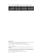
The function library LenzeCanDSxDrv.lib can be used for the following Lenze PLCs: 9300 Servo PLC 9300 Servo PLC Drive PLC ECSxA Type from hardware version from software version EVS93XX−xI EVS93XX−xT 6A 6A 6.0 6.0 EPL10200 ECSxAxxx 1A 1C 6.0 7.0 Important note: The software is supplied to the user as described in this document. Any risks resulting from its quality or use remain the responsibility of the user. The user must provide all safety measures protecting against possible maloperation.
Function library LenzeCanDSxDrv.lib Contents 1 Preface and general information . . . . . . . . . . . . . . . . . . . . . . . . . . . . . . . . . . . . . . . . . . . 1−1 1.1 About this Manual . . . . . . . . . . . . . . . . . . . . . . . . . . . . . . . . . . . . . . . . . . . . . . . . . . . . . . . . . . . . . . . . . 1.1.1 Conventions in this Manual . . . . . . . . . . . . . . . . . . . . . . . . . . . . . . . . . . . . . . . . . . . . . . . . . . . 1.1.2 Description layout . . . . . . . . . . . . . .
Function library LenzeCanDSxDrv.lib Contents ii LenzeCanDSxDrv.lib EN 1.
Function library LenzeCanDSxDrv.lib Preface and general information 1.1 About this Manual 1 Preface and general information 1.1 About this Manual This Manual contains information about function library LenzeCanDSxDrv.lib for the Drive PLC Developer Studio. · With the functions of function library LenzeCanDSxDrv.lib it is possible to "map" CAN indices received via the system bus interface within the PLC on codes other than the automatically assigned codes.
Function library LenzeCanDSxDrv.lib Preface and general information 1.1 1.1.
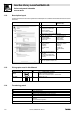
Function library LenzeCanDSxDrv.lib Preface and general information 1.2 1.2 Version identifiers of the function library Version identifiers of the function library The version of the function library can C_w[Function library name]Version . be found under the global constant Version identifiers as of PLC software version 7.
Function library LenzeCanDSxDrv.lib Preface and general information 1−4 LenzeCanDSxDrv.lib EN 1.
Function library LenzeCanDSxDrv.lib Introduction 2.1 General information 2 Introduction 2.1 General information The communication behaviour of the CAN bus devices is defined in a variety of communication profiles for CAN communication, e. g.
Function library LenzeCanDSxDrv.lib Introduction 2.2 2.2.1 CanDSx driver Operating principle − example Task A user has implemented a functionality in his PLC which can be parameterised under user code C3200/5. Code C3200 is automatically assigned to the index dec: Index = 24575dec − code = 24575dec − 3200 = 21375dec The communication profile requires, however, that the functionality is parameterised under the index 4101 dec/subindex 2. Solution Use the functions of function library LenzeCanDSxDrv.
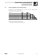
Function library LenzeCanDSxDrv.lib Introduction 2.3 2.3 Monitoring mechanisms Monitoring mechanisms The CANopen communication profile (CiA DS301, version 4.01) specifies two optional monitoring mechanisms to ensure the functionality of the system bus devices: "Heartbeat" and "Node Guarding". 2.3.1 "Heartbeat" The "Heartbeat" monitoring mechanism is a producer−consumer orientated method. Every bus device can monitor the state of the other bus devices. A polling message is not required.
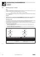
Function library LenzeCanDSxDrv.lib Introduction 2.3 2.3.2 Monitoring mechanisms "Node Guarding" Unlike the "Heartbeat" monitoring mechanism, "Node Guarding" requires a polling message from the monitoring bus device (NMT master).
Function library LenzeCanDSxDrv.lib Functions/function blocks 3.1 Overview 3 Functions/function blocks 3.1 Overview Function/FB Info Index mapping on codes · The functions only refer to parameter access via the system bus interface of the PLC.
Function library LenzeCanDSxDrv.lib Functions/function blocks 3.2 3.2 L_CanDSxInitIndexCode − Configuration of index mapping L_CanDSxInitIndexCode − Configuration of index mapping Function This function is used to configure the mapping table and the redirection of indeces to codes other than the automatically assigned codes. · With every function call one index and the corresponding Lenze code can be entered in the mapping table.
Function library LenzeCanDSxDrv.lib Functions/function blocks 3.2 L_CanDSxInitIndexCode − Configuration of index mapping Example Calling the function in ST: nReturnInitIndexCode := L_CanDSxInitIndexCode(byTabIndex:=1, wCANIndex:=4101, byCANSubIndex:=2, wLenzeCodeNumber:=3200, byLenzeSubCodeNumber:=5); L LenzeCanDSxDrv.lib EN 1.
Function library LenzeCanDSxDrv.lib Functions/function blocks 3.3 3.3 L_CanDSxOpen − Initialisation of the CanDSx driver L_CanDSxOpen − Initialisation of the CanDSx driver Function This function is used to initialise the CanDSx driver in the operating system of the PLC. · For initialisation, the transfer parameter bOpen must be TRUE.
Function library LenzeCanDSxDrv.lib Functions/function blocks 3.4 3.4 L_CanDSxClose − Deactivation of index mapping L_CanDSxClose − Deactivation of index mapping Function This function is used to deactivate the mapping table and the redirection of indeces. · For deactivation, the transfer parameter bClose must be set to TRUE. · After this function has been executed, the indeces accessed via the system bus interface will no longer be redirected to the corresponding codes of the mapping table.
Function library LenzeCanDSxDrv.lib Functions/function blocks 3.5 3.5 L_CanDSxOpenHeartBeat − Initialisation of "Heartbeat" L_CanDSxOpenHeartBeat − Initialisation of "Heartbeat" Function The CANopen communication profile (CiA DS301, version 4.01) specifies two optional monitoring mechanisms to ensure the functionality of the system bus devices: "Heartbeat" and "Node Guarding". This function is used to initialise the "Heartbeat" monitoring mechanism of the CanDSx driver.
Function library LenzeCanDSxDrv.lib Functions/function blocks 3.6 3.6 L_CanDSxHeartBeat − Execution of "Heartbeat" L_CanDSxHeartBeat − Execution of "Heartbeat" Function block This FB is used for the cyclic monitoring of the CAN connection between the PLC and other system bus devices by means of the "Heartbeat" mechanism. · The FB acts as "Heartbeat consumer". For this, it must be activated in the monitoring PLC.
Function library LenzeCanDSxDrv.lib Functions/function blocks 3.6 L_CanDSxHeartBeat − Execution of "Heartbeat" Outputs Data type nState Information/possible settings Integer Status 300 FB is deactivated ( bRun = FALSE). 127 Bus device to be monitored is in CAN state Pre−operational. 5 Bus device to be monitored is in CAN state Operational. 4 Bus device to be monitored is in CAN state Stopped. 0 Bus device to be monitored is in CAN state Boot−up or FB is not activated.
Function library LenzeCanDSxDrv.lib Functions/function blocks 3.7 3.7 L_CanDSxCloseHeartBeat − Deactivation of "Heartbeat" L_CanDSxCloseHeartBeat − Deactivation of "Heartbeat" Function This function is used to deactivate the "Heartbeat" monitoring mechanism of the CanDSx driver. · For deactivation, the transfer parameter bClose must be set to TRUE.
Function library LenzeCanDSxDrv.lib Functions/function blocks 3.8 3.8 L_CanDSxOpenNodeGuarding − Initialisation of "Node Guarding" L_CanDSxOpenNodeGuarding − Initialisation of "Node Guarding" Function The CANopen communication profile (CiA DS301, version 4.01) specifies two optional monitoring mechanisms to ensure the functionality of the system bus devices: "Heartbeat" and "Node Guarding". This function is used to initialise the "Node Guarding" monitoring mechanism of the CanDSx driver.
Function library LenzeCanDSxDrv.lib Functions/function blocks 3.9 3.9 L_CanDSxNodeGuarding − Execution of "Node Guarding" L_CanDSxNodeGuarding − Execution of "Node Guarding" Function block This FB is used for the cyclic monitoring of the CAN connection between the PLC and other system bus devices by means of the "Node Guarding" mechanism.
Function library LenzeCanDSxDrv.lib Functions/function blocks 3.9 L_CanDSxNodeGuarding − Execution of "Node Guarding" Outputs Data type nState Information/possible settings Integer Status 300 FB is deactivated (bRun= FALSE). 127 Bus device to be monitored is in CAN state Pre−operational. 5 Bus device to be monitored is in CAN state Operational. 4 Bus device to be monitored is in CAN state Stopped. 0 Bus device to be monitored is in CAN state Boot−up or FB is not activated.
Function library LenzeCanDSxDrv.lib Functions/function blocks 3.9 L_CanDSxNodeGuarding − Execution of "Node Guarding" 4. Use C0383 to select the factor for the monitoring time ("NodeLifeTime") in the PLC to be monitored. The value must correspond to the setting at the FB input byNodeLifeTimeFactor: Code Possible settings LCD Lenze C0383 LifeTimeFact.
Function library LenzeCanDSxDrv.lib Functions/function blocks 3.10 3.10 L_CanDSxCloseNodeGuarding − Deactivation of "Node Guarding" L_CanDSxCloseNodeGuarding − Deactivation of "Node Guarding" Function This function is used to deactivate the "Node Guarding" monitoring mechanism of the CanDSx driver. · For deactivation, the transfer parameter bClose must be set to TRUE.