
Instruction Manual
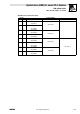
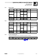
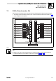
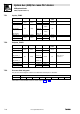
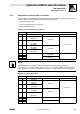
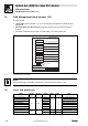
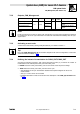
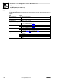
Table Of Contents
- System bus (CAN) for Lenze PLC devices
- This documentation is valid for ...
- Contents
- 1 Preface and general information
- 2 General information on the system bus (CAN)
- 2.1 Introduction
- 2.2 Interfaces of the Lenze PLCs for system bus connection
- 2.3 Identification of the nodes
- 2.4 Structure of the CAN telegram
- 2.5 Network management (NMT)
- 2.6 Transmission of process data
- 2.7 Transmitting parameter data
- 2.8 Free CAN objects
- 2.9 Application recommendations for the different CAN objects
- 2.10 Monitoring mechanisms
- 3 Configuration (system bus - CAN interface)
- 3.1 CAN baud rate
- 3.2 CAN boot-up
- 3.3 Node address (node ID)
- 3.4 Identifiers of the process data objects
- 3.5 Cycle time (CAN2_OUT/CAN3_OUT)
- 3.6 Delay time (CAN2_OUT/CAN3_OUT)
- 3.7 Synchronisation
- 3.8 Reset node
- 3.9 System bus management
- 3.10 Mapping indexes to codes
- 3.11 Remote parameterisation (gateway function)
- 3.12 Monitoring processes
- 3.13 Diagnostics
- 4 Configuration (AIF interface)
- 5 Configuration (FIF interface)
- 6 Configuration (CAN-AUX system bus interface)
- 7 CAN system blocks
- 8 FIF-CAN system blocks (only Drive PLC)
- 9 CAN-AUX system blocks (only ECSxA)
- 10 LenzeCanDrv.lib function library
- 10.1 Overview
- 10.2 Version identifiers of the function library
- 10.3 L_CanInit - initialising the CAN driver
- 10.4 L_CanClose - deactivating the CAN driver
- 10.5 L_CanGetStatus - querying the driver status
- 10.6 L_CanGetRelocCobId - querying the COB-ID range
- 10.7 L_CanPdoTransmit - transmitting a CAN object
- 10.8 L_CanPdoReceive - receiving a CAN object
- 11 LenzeCanDSxDrv.libfunction library
- 11.1 Overview
- 11.2 Version identifiers of the function library
- 11.3 L_CanDSxInitIndexCode - Configuration of index mapping
- 11.4 L_CanDSxOpen - initialising the CanDSx driver
- 11.5 L_CanDSxClose - deactivating the index mapping
- 11.6 L_CanDSxOpenHeartBeat - initialising a "Heartbeat"
- 11.7 L_CanDSxHeartBeat - carrying out a "Heartbeat"
- 11.8 L_CanDSxCloseHeartBeat - deactivating the "Heartbeat"
- 11.9 L_CanDSxOpenNodeGuarding - initialising the "Node Guarding"
- 11.10 L_CanDSxNodeGuarding - carrying out a "Node guarding"
- 11.11 L_CanDSxCloseNodeGuarding - deactivating the "Node Guarding"
- 12 Index
System bus (CAN) for Lenze PLC devices
CAN system blocks
7.5 CAN3_IO (node number: 33)
7−19
L
PLC−Systembus EN 2.0
7.5.4 Assignment of the user data to variables
Several variables of different data types are assigned to the user data to be transmitted and received.
Thus, the data in the PLC program can be optionally interpreted as:
· binary information (1 bit)
· status word/quasi−analog value (16 bit)
· angle information (32 bit)
Variables for user data to be transmitted
User data Assigned variables
Byte Bit Variable (1 bit) Variable (16 bit) Variable (32 bit)
1 0
...
7
CAN3_bFDO0_b
...
CAN3_bFDO7_b
CAN3_nOutW1_a
CAN3_dnOutD1_p
2 0
...
7
CAN3_bFDO8_b
...
CAN3_bFDO15_b
3 0
...
7
CAN3_bFDO16_b
...
CAN3_bFDO23_b
CAN3_nOutW2_a
4 0
...
7
CAN3_bFDO24_b
...
CAN3_bFDO31_b
5 0...7
CAN3_nOutW3_a
6 0...7
7 0...7
CAN3_nOutW4_a
8 0...7
Note!
Avoid simultaneous overwriting via different variable types to ensure data consistency.
For instance, if you want to write bytes 1 and 2, only use the variable CAN3_dnOutD1_p,
CAN3_nOutW1_a, or only the variables CAN3_bFDO0_b ... CAN3_bFDO15_b for this purpose!
Variables for received user data
User data Assigned variables
Byte Bit Variable (1 bit) Variable (16 bit) Variable (32 bit)
1 0
...
7
CAN3_bInB0_b
...
CAN3_bInB7_b
CAN3_nInW1_a
CAN3_dnInD1_p
2 0
...
7
CAN3_bInB8_b
...
CAN3_bInB15_b
3 0
...
7
CAN3_bInB16_b
...
CAN3_bInB23_b
CAN3_nInW2_a
4 0
...
7
CAN3_bInB24_b
...
CAN3_bInB31_b
5 0...7
CAN3_nInW3_a
6 0...7
7 0...7
CAN3_nInW4_a
8 0...7