
Instruction Manual
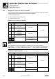
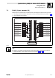
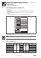
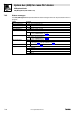
Table Of Contents
- System bus (CAN) for Lenze PLC devices
- This documentation is valid for ...
- Contents
- 1 Preface and general information
- 2 General information on the system bus (CAN)
- 2.1 Introduction
- 2.2 Interfaces of the Lenze PLCs for system bus connection
- 2.3 Identification of the nodes
- 2.4 Structure of the CAN telegram
- 2.5 Network management (NMT)
- 2.6 Transmission of process data
- 2.7 Transmitting parameter data
- 2.8 Free CAN objects
- 2.9 Application recommendations for the different CAN objects
- 2.10 Monitoring mechanisms
- 3 Configuration (system bus - CAN interface)
- 3.1 CAN baud rate
- 3.2 CAN boot-up
- 3.3 Node address (node ID)
- 3.4 Identifiers of the process data objects
- 3.5 Cycle time (CAN2_OUT/CAN3_OUT)
- 3.6 Delay time (CAN2_OUT/CAN3_OUT)
- 3.7 Synchronisation
- 3.8 Reset node
- 3.9 System bus management
- 3.10 Mapping indexes to codes
- 3.11 Remote parameterisation (gateway function)
- 3.12 Monitoring processes
- 3.13 Diagnostics
- 4 Configuration (AIF interface)
- 5 Configuration (FIF interface)
- 6 Configuration (CAN-AUX system bus interface)
- 7 CAN system blocks
- 8 FIF-CAN system blocks (only Drive PLC)
- 9 CAN-AUX system blocks (only ECSxA)
- 10 LenzeCanDrv.lib function library
- 10.1 Overview
- 10.2 Version identifiers of the function library
- 10.3 L_CanInit - initialising the CAN driver
- 10.4 L_CanClose - deactivating the CAN driver
- 10.5 L_CanGetStatus - querying the driver status
- 10.6 L_CanGetRelocCobId - querying the COB-ID range
- 10.7 L_CanPdoTransmit - transmitting a CAN object
- 10.8 L_CanPdoReceive - receiving a CAN object
- 11 LenzeCanDSxDrv.libfunction library
- 11.1 Overview
- 11.2 Version identifiers of the function library
- 11.3 L_CanDSxInitIndexCode - Configuration of index mapping
- 11.4 L_CanDSxOpen - initialising the CanDSx driver
- 11.5 L_CanDSxClose - deactivating the index mapping
- 11.6 L_CanDSxOpenHeartBeat - initialising a "Heartbeat"
- 11.7 L_CanDSxHeartBeat - carrying out a "Heartbeat"
- 11.8 L_CanDSxCloseHeartBeat - deactivating the "Heartbeat"
- 11.9 L_CanDSxOpenNodeGuarding - initialising the "Node Guarding"
- 11.10 L_CanDSxNodeGuarding - carrying out a "Node guarding"
- 11.11 L_CanDSxCloseNodeGuarding - deactivating the "Node Guarding"
- 12 Index
7.6 CAN_Management (node number: 101)
System bus (CAN) for Lenze PLC devices
CAN system blocks
7−22
L
PLC−Systembus EN 2.0
7.6.5 Status messages
The CAN_Management SB provides different status messages which can be processed in the PLC
program:
Variable Description
CAN_bCe1CommErrCanIn1_b TRUE CAN1_IN communication error
CAN_bCe2CommErrCanIn1_b TRUE CAN2_IN communication error
CAN_bCe3CommErrCanIn1_b TRUE CAN3_IN communication error
CAN_bCe4BusOffState_b TRUE CAN bus "off state" recognised
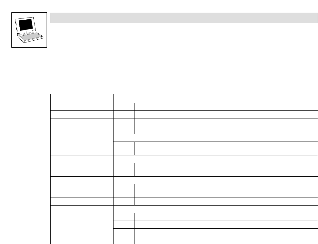
CAN_bFreePdoTxBufferOverflow_b
Free CAN objects
TRUE Overflow of send order memory
· See L_CanPdoTransmit FB. (^ 10−8)
CAN_bFreePdoRxOverflow_b
Free CAN objects
TRUE Overflow of the receive memory
· See L_CanPdoReceive FB. (^ 10−12)
CAN_bOverrunLifeTime_b
CAN"Node guarding" monitoring mechanism
TRUE The "Node life time" has been exceeded
· See chapter 2.10, "monitoring mechanisms". (^ 2−21)
CAN_byNodeAddress 1...63 CAN node address (^ 3−3)
CAN_byState
Operating status of the system bus
1 Operational
2 Pre−operational
3 Warning
4 Bus−off