
Instruction Manual
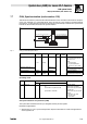
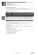
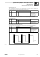
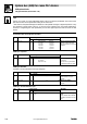
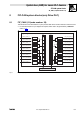
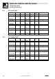
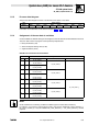
Table Of Contents
- System bus (CAN) for Lenze PLC devices
- This documentation is valid for ...
- Contents
- 1 Preface and general information
- 2 General information on the system bus (CAN)
- 2.1 Introduction
- 2.2 Interfaces of the Lenze PLCs for system bus connection
- 2.3 Identification of the nodes
- 2.4 Structure of the CAN telegram
- 2.5 Network management (NMT)
- 2.6 Transmission of process data
- 2.7 Transmitting parameter data
- 2.8 Free CAN objects
- 2.9 Application recommendations for the different CAN objects
- 2.10 Monitoring mechanisms
- 3 Configuration (system bus - CAN interface)
- 3.1 CAN baud rate
- 3.2 CAN boot-up
- 3.3 Node address (node ID)
- 3.4 Identifiers of the process data objects
- 3.5 Cycle time (CAN2_OUT/CAN3_OUT)
- 3.6 Delay time (CAN2_OUT/CAN3_OUT)
- 3.7 Synchronisation
- 3.8 Reset node
- 3.9 System bus management
- 3.10 Mapping indexes to codes
- 3.11 Remote parameterisation (gateway function)
- 3.12 Monitoring processes
- 3.13 Diagnostics
- 4 Configuration (AIF interface)
- 5 Configuration (FIF interface)
- 6 Configuration (CAN-AUX system bus interface)
- 7 CAN system blocks
- 8 FIF-CAN system blocks (only Drive PLC)
- 9 CAN-AUX system blocks (only ECSxA)
- 10 LenzeCanDrv.lib function library
- 10.1 Overview
- 10.2 Version identifiers of the function library
- 10.3 L_CanInit - initialising the CAN driver
- 10.4 L_CanClose - deactivating the CAN driver
- 10.5 L_CanGetStatus - querying the driver status
- 10.6 L_CanGetRelocCobId - querying the COB-ID range
- 10.7 L_CanPdoTransmit - transmitting a CAN object
- 10.8 L_CanPdoReceive - receiving a CAN object
- 11 LenzeCanDSxDrv.libfunction library
- 11.1 Overview
- 11.2 Version identifiers of the function library
- 11.3 L_CanDSxInitIndexCode - Configuration of index mapping
- 11.4 L_CanDSxOpen - initialising the CanDSx driver
- 11.5 L_CanDSxClose - deactivating the index mapping
- 11.6 L_CanDSxOpenHeartBeat - initialising a "Heartbeat"
- 11.7 L_CanDSxHeartBeat - carrying out a "Heartbeat"
- 11.8 L_CanDSxCloseHeartBeat - deactivating the "Heartbeat"
- 11.9 L_CanDSxOpenNodeGuarding - initialising the "Node Guarding"
- 11.10 L_CanDSxNodeGuarding - carrying out a "Node guarding"
- 11.11 L_CanDSxCloseNodeGuarding - deactivating the "Node Guarding"
- 12 Index
System bus (CAN) for Lenze PLC devices
CAN system blocks
7.7 CAN_Synchronization (node number: 102)
7−25
L
PLC−Systembus EN 2.0
Synchronisation cycle
The controllers/PLCs receive the sync telegram/signal and compare the time between two
LOW−HIGH edges of the signal to the specified cycle time (C1121).
Code LCD
Possible settings
IMPORTANT
Lenze Selection
[C1121] Sync cycle 2 1 {1 ms} 13 Synchronisation cycle
Definition of the cycle time of the
sync telegram/signal.
· Parameterisation is only
required for the slave!
· The value set in C1121 is the time between two sync telegrams/signals of the master.
Phase displacement
Code LCD
Possible settings
IMPORTANT
Lenze Selection
[C1122] Sync phase 0.460 0 {0.001 ms} 6.5 Synchronisation phase
Phase shift between the sync
telegram/signal and the start of the
internal control program.
Monitoring the synchronisation (time slot)
The variable CAN_bSyncInsideWindow_b can be used for monitoring the synchronisation.
Code LCD
Possible settings
IMPORTANT
Lenze Selection
[C1123] Sync window 0 0 {0.001 ms} 6.5 Synchronisation window
If the sync telegram/signal sent by
the master is in this "time slot",
CAN_bSyncInsideWindow_b
switches to TRUE.
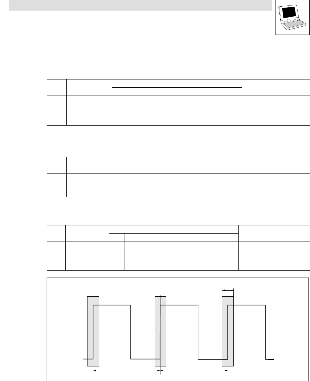
Sync signal
Sync window
SyncCycle SyncCycle
Fig. 7−8 "Time slot" for the LOW−HIGH edges of the sync signal