
Instruction Manual
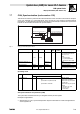
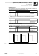
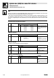
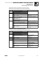
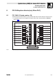
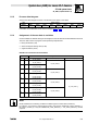
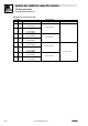
Table Of Contents
- System bus (CAN) for Lenze PLC devices
- This documentation is valid for ...
- Contents
- 1 Preface and general information
- 2 General information on the system bus (CAN)
- 2.1 Introduction
- 2.2 Interfaces of the Lenze PLCs for system bus connection
- 2.3 Identification of the nodes
- 2.4 Structure of the CAN telegram
- 2.5 Network management (NMT)
- 2.6 Transmission of process data
- 2.7 Transmitting parameter data
- 2.8 Free CAN objects
- 2.9 Application recommendations for the different CAN objects
- 2.10 Monitoring mechanisms
- 3 Configuration (system bus - CAN interface)
- 3.1 CAN baud rate
- 3.2 CAN boot-up
- 3.3 Node address (node ID)
- 3.4 Identifiers of the process data objects
- 3.5 Cycle time (CAN2_OUT/CAN3_OUT)
- 3.6 Delay time (CAN2_OUT/CAN3_OUT)
- 3.7 Synchronisation
- 3.8 Reset node
- 3.9 System bus management
- 3.10 Mapping indexes to codes
- 3.11 Remote parameterisation (gateway function)
- 3.12 Monitoring processes
- 3.13 Diagnostics
- 4 Configuration (AIF interface)
- 5 Configuration (FIF interface)
- 6 Configuration (CAN-AUX system bus interface)
- 7 CAN system blocks
- 8 FIF-CAN system blocks (only Drive PLC)
- 9 CAN-AUX system blocks (only ECSxA)
- 10 LenzeCanDrv.lib function library
- 10.1 Overview
- 10.2 Version identifiers of the function library
- 10.3 L_CanInit - initialising the CAN driver
- 10.4 L_CanClose - deactivating the CAN driver
- 10.5 L_CanGetStatus - querying the driver status
- 10.6 L_CanGetRelocCobId - querying the COB-ID range
- 10.7 L_CanPdoTransmit - transmitting a CAN object
- 10.8 L_CanPdoReceive - receiving a CAN object
- 11 LenzeCanDSxDrv.libfunction library
- 11.1 Overview
- 11.2 Version identifiers of the function library
- 11.3 L_CanDSxInitIndexCode - Configuration of index mapping
- 11.4 L_CanDSxOpen - initialising the CanDSx driver
- 11.5 L_CanDSxClose - deactivating the index mapping
- 11.6 L_CanDSxOpenHeartBeat - initialising a "Heartbeat"
- 11.7 L_CanDSxHeartBeat - carrying out a "Heartbeat"
- 11.8 L_CanDSxCloseHeartBeat - deactivating the "Heartbeat"
- 11.9 L_CanDSxOpenNodeGuarding - initialising the "Node Guarding"
- 11.10 L_CanDSxNodeGuarding - carrying out a "Node guarding"
- 11.11 L_CanDSxCloseNodeGuarding - deactivating the "Node Guarding"
- 12 Index
7.7 CAN_Synchronization (node number: 102)
System bus (CAN) for Lenze PLC devices
CAN system blocks
7−26
L
PLC−Systembus EN 2.0
Tip!
A jitter* up to ±200 ms on the LOW−HIGH edges of the sync signal is permissible. The extent of the
jitter has an effect on the parameter setting of the "time slot".
* Jitter refers to the phase shiftings and therefore to the periodic changes of signal frequencies. They
are variations of fixed points in time (e. g. the time of the transition from one signal amplitude to
another) of a digital signal. Jitter particularly occurs with high frequencies and can result in data
losses.
Correction value of the phase controller
Code LCD
Possible settings
IMPORTANT
Lenze Selection
C0363 Sync corr 1 9300 Servo PLC: Drive PLC:
1 0.2 ms/ms 0.4 ms/ms
2 0.4 ms/ms 0.8 ms/ms
3 0.6 ms/ms 1.2 ms/ms
4 0.8 ms/ms 1.6 ms/ms
5 1.0 ms/ms 2.0 ms/ms
CAN sync correction increment
Alter the correction value until
CAN_nSyncDeviation has reached a
minimum.
CAN sync response
Code LCD
Possible settings
IMPORTANT
Lenze Selection
C0366 Sync response 1 CAN sync response
0 No response No response
1 Response to sync PLC responds to a sync telegram
by sending the CAN1_OUT object.
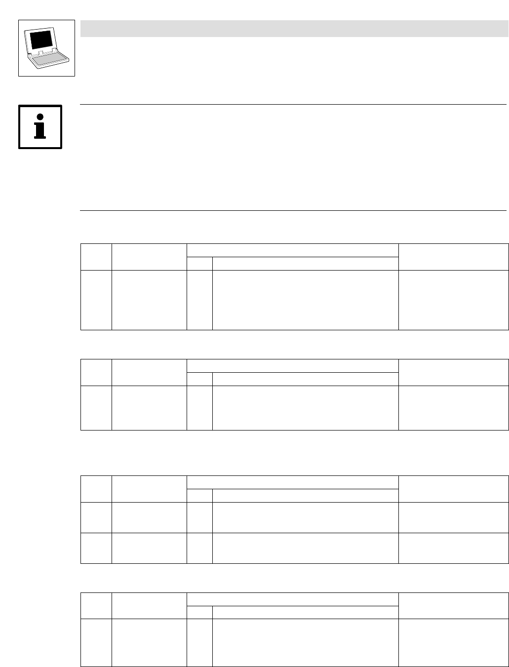
CAN sync identifier
Transmit or receive identifier of the sync telegram
Code LCD
Possible settings
IMPORTANT
Lenze Selection
C0367 Sync Rx Id 128 1 {1} 256 CAN sync Rx identifier
Receive identifier of the sync
telegram.
C0368 Sync Tx Id 128 1 {1} 256 CAN sync Tx identifier
Send identifier of the sync
telegram.
CAN sync Tx transmission cycle
Code LCD
Possible settings
IMPORTANT
Lenze Selection
C0369 Sync Tx time 0 0 {1} 65000
0 = Off
CAN sync transmission telegram
cycle
A sync telegram with the identifier
of C0368 is sent with the set cycle
time.