
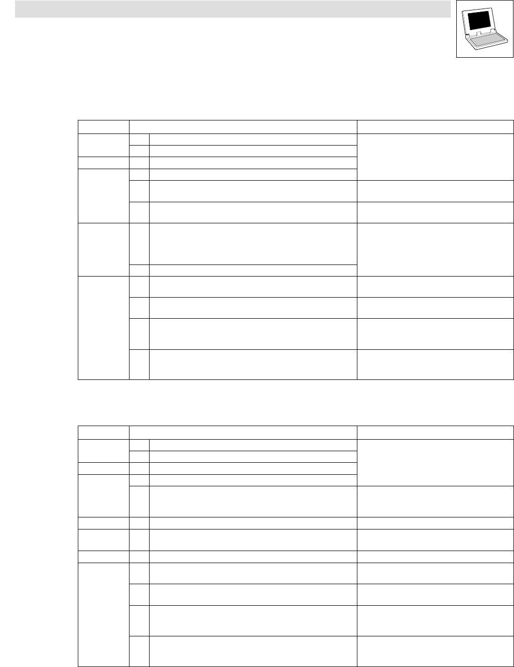
Instruction Manual
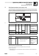
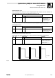
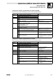
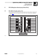
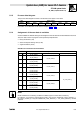
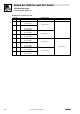
Table Of Contents
- System bus (CAN) for Lenze PLC devices
- This documentation is valid for ...
- Contents
- 1 Preface and general information
- 2 General information on the system bus (CAN)
- 2.1 Introduction
- 2.2 Interfaces of the Lenze PLCs for system bus connection
- 2.3 Identification of the nodes
- 2.4 Structure of the CAN telegram
- 2.5 Network management (NMT)
- 2.6 Transmission of process data
- 2.7 Transmitting parameter data
- 2.8 Free CAN objects
- 2.9 Application recommendations for the different CAN objects
- 2.10 Monitoring mechanisms
- 3 Configuration (system bus - CAN interface)
- 3.1 CAN baud rate
- 3.2 CAN boot-up
- 3.3 Node address (node ID)
- 3.4 Identifiers of the process data objects
- 3.5 Cycle time (CAN2_OUT/CAN3_OUT)
- 3.6 Delay time (CAN2_OUT/CAN3_OUT)
- 3.7 Synchronisation
- 3.8 Reset node
- 3.9 System bus management
- 3.10 Mapping indexes to codes
- 3.11 Remote parameterisation (gateway function)
- 3.12 Monitoring processes
- 3.13 Diagnostics
- 4 Configuration (AIF interface)
- 5 Configuration (FIF interface)
- 6 Configuration (CAN-AUX system bus interface)
- 7 CAN system blocks
- 8 FIF-CAN system blocks (only Drive PLC)
- 9 CAN-AUX system blocks (only ECSxA)
- 10 LenzeCanDrv.lib function library
- 10.1 Overview
- 10.2 Version identifiers of the function library
- 10.3 L_CanInit - initialising the CAN driver
- 10.4 L_CanClose - deactivating the CAN driver
- 10.5 L_CanGetStatus - querying the driver status
- 10.6 L_CanGetRelocCobId - querying the COB-ID range
- 10.7 L_CanPdoTransmit - transmitting a CAN object
- 10.8 L_CanPdoReceive - receiving a CAN object
- 11 LenzeCanDSxDrv.libfunction library
- 11.1 Overview
- 11.2 Version identifiers of the function library
- 11.3 L_CanDSxInitIndexCode - Configuration of index mapping
- 11.4 L_CanDSxOpen - initialising the CanDSx driver
- 11.5 L_CanDSxClose - deactivating the index mapping
- 11.6 L_CanDSxOpenHeartBeat - initialising a "Heartbeat"
- 11.7 L_CanDSxHeartBeat - carrying out a "Heartbeat"
- 11.8 L_CanDSxCloseHeartBeat - deactivating the "Heartbeat"
- 11.9 L_CanDSxOpenNodeGuarding - initialising the "Node Guarding"
- 11.10 L_CanDSxNodeGuarding - carrying out a "Node guarding"
- 11.11 L_CanDSxCloseNodeGuarding - deactivating the "Node Guarding"
- 12 Index
System bus (CAN) for Lenze PLC devices
CAN system blocks
7.7 CAN_Synchronization (node number: 102)
7−27
L
PLC−Systembus EN 2.0
Configuration example: synchronisation via system bus (CAN)
When carrying out the commissioning, observe the following sequence:
Location Step Information
All devices
1. Commission controller/PLC and system bus.
2. Inhibit controller/PLC.
DDS 3. Integrate CAN_Synchronization SB into the control configuration.
Slave devices
4. Connect CAN_bSyncInsideWindow_b to a digital output.
5. C1120 = 1 Synchronisation by sync telegram via system bus
active.
6. C0366 = 1 (Lenze setting) CAN sync response:
Slave devices respond to sync telegram.
Master
7. Define order of the telegrams (identifiers):
1. Send new setpoint to all slaves
2. Send sync telegram
3. Receive response of all slaves
8. Start communication / send sync telegrams.
Slave devices
9. Read C0362 from the master. Query cycle time of the sync telegram from the
master.
10. Set C1121 in accordance with C0362 from the master. Adjust interval of the sync telegrams to be
received to the cycle time of the master.
11. Set C1123. Set optimum size for the "time slot".
· If the sync signal "jitters" heavily, increase
"time slot".
12. Enable controller/PLC via the signal CAN_bSyncInsideWindow_b
applied to the digital output.
Monitor the synchronisation.
· If CAN_bSyncInsideWindow_b = TRUE, enable
controller/PLC.
Configuration example: synchronisation via terminal
When carrying out the commissioning, observe the following sequence:
Location Step Information
All devices
1. Commission controller/PLC and system bus.
2. Inhibit controller/PLC.
DDS 3. Integrate CAN_Synchronization SB into the control configuration.
Slave devices
4. Connect CAN_bSyncInsideWindow_b to a digital output.
5. Apply sync signal of the master to terminal. 9300 Servo PLC: terminal X5/E5
Drive PLC: terminal X3/I1
ECSxA: X6/DI1
Slave devices 6. C1120 = 2 Synchronisation by sync signal via terminal active.
Slave devices 7. C0366 = 1 (Lenze setting) CAN sync response:
Slave devices respond to sync telegram.
Master 8. Start communication, send sync telegrams.
Slave devices
9. Read C0362 from the master. Query cycle time of the sync signal from the
master.
10. Set C1121 in accordance with C0362 from the master. Adjust interval of the sync signals to be received
to the cycle time of the master.
11. Set C1123. Set optimum size for the "time slot".
· If the sync signal "jitters" heavily, increase
"time slot".
12. Enable controller/PLC via the signal CAN_bSyncInsideWindow_b
applied to the digital output.
Monitor the synchronisation.
· If CAN_bSyncInsideWindow_b = TRUE, enable
controller/PLC.