
Instruction Manual
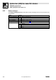
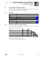
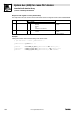
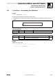
Table Of Contents
- System bus (CAN) for Lenze PLC devices
- This documentation is valid for ...
- Contents
- 1 Preface and general information
- 2 General information on the system bus (CAN)
- 2.1 Introduction
- 2.2 Interfaces of the Lenze PLCs for system bus connection
- 2.3 Identification of the nodes
- 2.4 Structure of the CAN telegram
- 2.5 Network management (NMT)
- 2.6 Transmission of process data
- 2.7 Transmitting parameter data
- 2.8 Free CAN objects
- 2.9 Application recommendations for the different CAN objects
- 2.10 Monitoring mechanisms
- 3 Configuration (system bus - CAN interface)
- 3.1 CAN baud rate
- 3.2 CAN boot-up
- 3.3 Node address (node ID)
- 3.4 Identifiers of the process data objects
- 3.5 Cycle time (CAN2_OUT/CAN3_OUT)
- 3.6 Delay time (CAN2_OUT/CAN3_OUT)
- 3.7 Synchronisation
- 3.8 Reset node
- 3.9 System bus management
- 3.10 Mapping indexes to codes
- 3.11 Remote parameterisation (gateway function)
- 3.12 Monitoring processes
- 3.13 Diagnostics
- 4 Configuration (AIF interface)
- 5 Configuration (FIF interface)
- 6 Configuration (CAN-AUX system bus interface)
- 7 CAN system blocks
- 8 FIF-CAN system blocks (only Drive PLC)
- 9 CAN-AUX system blocks (only ECSxA)
- 10 LenzeCanDrv.lib function library
- 10.1 Overview
- 10.2 Version identifiers of the function library
- 10.3 L_CanInit - initialising the CAN driver
- 10.4 L_CanClose - deactivating the CAN driver
- 10.5 L_CanGetStatus - querying the driver status
- 10.6 L_CanGetRelocCobId - querying the COB-ID range
- 10.7 L_CanPdoTransmit - transmitting a CAN object
- 10.8 L_CanPdoReceive - receiving a CAN object
- 11 LenzeCanDSxDrv.libfunction library
- 11.1 Overview
- 11.2 Version identifiers of the function library
- 11.3 L_CanDSxInitIndexCode - Configuration of index mapping
- 11.4 L_CanDSxOpen - initialising the CanDSx driver
- 11.5 L_CanDSxClose - deactivating the index mapping
- 11.6 L_CanDSxOpenHeartBeat - initialising a "Heartbeat"
- 11.7 L_CanDSxHeartBeat - carrying out a "Heartbeat"
- 11.8 L_CanDSxCloseHeartBeat - deactivating the "Heartbeat"
- 11.9 L_CanDSxOpenNodeGuarding - initialising the "Node Guarding"
- 11.10 L_CanDSxNodeGuarding - carrying out a "Node guarding"
- 11.11 L_CanDSxCloseNodeGuarding - deactivating the "Node Guarding"
- 12 Index
10.3 L_CanInit − initialising the CAN driver
System bus (CAN) for Lenze PLC devices
LenzeCanDrv.lib function library
10−4
L
PLC−Systembus EN 2.0
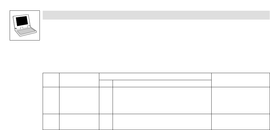
Response with regard to errors (Tx/Rx buffer)
The response in the case of errors in the Tx/Rx buffer can be configured via the codes C0608/C0609:
Code LCD
Possible settings
Information
Lenze Selection
C0608 over Tx−Queue 0 0 TRIP
1 Message
2 Warning
3 Off
4 FAIL QSP (not for Drive PLC!)
Configuration of the monitoring for
Tx buffer
C0609 over Rx−lsr 0 0 TRIP
4 Fail−QSP
Configuration of the monitoring for
Rx buffer
· Not for Drive PLC!
Example
Calling the function in ST with decoding of the return value:
(* open CAN driver − returns g_dwReturnValue *)
g_dwReturnValue:=L_CanInit(10, 0);
g_bInitOK := NOT DWORD_TO_BOOL(g_dwReturnValue AND 16#0000_0001);
g_bDriverFail := DWORD_TO_BOOL(SHR(g_dwReturnValue,1) AND 16#0000_0001);
g_wVersion := DWORD_TO_WORD(SHR(g_dwReturnValue,16) AND 16#FFFF);