
Instruction Manual
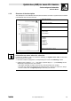

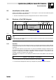
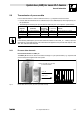
Table Of Contents
- System bus (CAN) for Lenze PLC devices
- This documentation is valid for ...
- Contents
- 1 Preface and general information
- 2 General information on the system bus (CAN)
- 2.1 Introduction
- 2.2 Interfaces of the Lenze PLCs for system bus connection
- 2.3 Identification of the nodes
- 2.4 Structure of the CAN telegram
- 2.5 Network management (NMT)
- 2.6 Transmission of process data
- 2.7 Transmitting parameter data
- 2.8 Free CAN objects
- 2.9 Application recommendations for the different CAN objects
- 2.10 Monitoring mechanisms
- 3 Configuration (system bus - CAN interface)
- 3.1 CAN baud rate
- 3.2 CAN boot-up
- 3.3 Node address (node ID)
- 3.4 Identifiers of the process data objects
- 3.5 Cycle time (CAN2_OUT/CAN3_OUT)
- 3.6 Delay time (CAN2_OUT/CAN3_OUT)
- 3.7 Synchronisation
- 3.8 Reset node
- 3.9 System bus management
- 3.10 Mapping indexes to codes
- 3.11 Remote parameterisation (gateway function)
- 3.12 Monitoring processes
- 3.13 Diagnostics
- 4 Configuration (AIF interface)
- 5 Configuration (FIF interface)
- 6 Configuration (CAN-AUX system bus interface)
- 7 CAN system blocks
- 8 FIF-CAN system blocks (only Drive PLC)
- 9 CAN-AUX system blocks (only ECSxA)
- 10 LenzeCanDrv.lib function library
- 10.1 Overview
- 10.2 Version identifiers of the function library
- 10.3 L_CanInit - initialising the CAN driver
- 10.4 L_CanClose - deactivating the CAN driver
- 10.5 L_CanGetStatus - querying the driver status
- 10.6 L_CanGetRelocCobId - querying the COB-ID range
- 10.7 L_CanPdoTransmit - transmitting a CAN object
- 10.8 L_CanPdoReceive - receiving a CAN object
- 11 LenzeCanDSxDrv.libfunction library
- 11.1 Overview
- 11.2 Version identifiers of the function library
- 11.3 L_CanDSxInitIndexCode - Configuration of index mapping
- 11.4 L_CanDSxOpen - initialising the CanDSx driver
- 11.5 L_CanDSxClose - deactivating the index mapping
- 11.6 L_CanDSxOpenHeartBeat - initialising a "Heartbeat"
- 11.7 L_CanDSxHeartBeat - carrying out a "Heartbeat"
- 11.8 L_CanDSxCloseHeartBeat - deactivating the "Heartbeat"
- 11.9 L_CanDSxOpenNodeGuarding - initialising the "Node Guarding"
- 11.10 L_CanDSxNodeGuarding - carrying out a "Node guarding"
- 11.11 L_CanDSxCloseNodeGuarding - deactivating the "Node Guarding"
- 12 Index
System bus (CAN) for Lenze PLC devices
General information
2−3
l
PLC−Systembus EN 2.0
2.3 Identification of the nodes
Assign a node address − also called Node ID − in the range of 1 to 63 to each node within the system
bus network as a definite identification.
· The same node address may not be assigned more than once within the network.
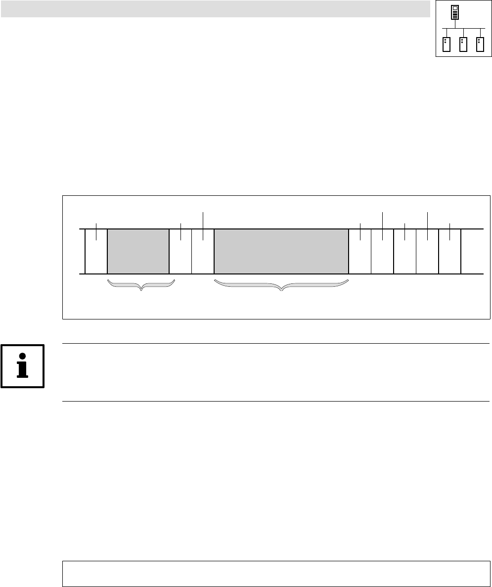
2.4 Structure of the CAN telegram
1bit 11bit 1bit 6bit
0 ... 8 byte
15bit
Start
Identifier
RTR bit
Control field
User data
CRC
sequence
CRC delimit.
ACK slot
ACK delimit.
End
Description see chapter 2.4.1
· Network management
· Parameter data
· Process data
Description see chapter 2.4.2
1bit 1bit 1bit 7bit
Fig. 2−1 Basic structure of a CAN telegram
Tip!
For the user only the identifier and the user data are relevant. All further data of the CAN telegram
are processed by the system.
2.4.1 Identifier
The principle of the CAN communication is based on a message−oriented data exchange between
a transmitter and many receivers. Thereby all nodes practically are able to transmit and receive at the
same time.
The control with regard to the node which is to receive a transmitted message is effected via the
so−called Identifier in the CAN telegram, also called COB−ID (Communication Object Identifier). For
purposes of addressing, the identifier additionally contains information on the priority of the
message, as well as on the type of the user data.
The identifier is composed of a so−called basic identifier and the node address of the node to be
activated:
Identifier + basic identifier ) node address
· For Lenze devices, the node address is defined via code C0350. (^ 3−3)
· For the network management and the sync telegram only the basic identifier is required.